Introduction
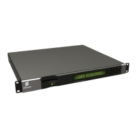
- Front Panel User Interface.
1.2.2 Inputs
1.2.2.1
1.2.2.2
1.2.2.3
1.2.2.4
1.2.2.5
1.2.2.6
1.2.3.1
1.2.3.2
1.2.3.3
ASI Input (Decoder)
One BNC connector supporting both byte-mode and single packet burst mode.
Remote Control
An RJ-45 Ethernet connector for connection to a PC or network switch to provide
SNMP control.
DVB-S / DVB-S2 L-Band Inputs (Satellite Receivers) (Option)
Four F-type connectors connect the L-band output of a suitable LNB either directly
or via a suitable attenuator giving lightning and surge protection.
TTV G.703 DS3 and E3 Input (Telco Receivers) (Option)
Equipped with a single BNC connector for receiving signals over a PDH Telco
network.
IP Input (Telco Receivers) (Option)
A single 10/100/1000BaseT RJ-45 connector for receiving signals over Ethernet
Frame Synchronization
A BNC connector accepts a composite video input to which the video output timing
can be synchronized.
1.2.3 Outputs
Transport Stream Outputs
• Up to three BNC connectors output ASI Transport Streams with a maximum
data rate of 160 Mbps, depending on the CA in use and the input card front-end.
Video Outputs
• One SVGA HD video output carried on a D-type connector for monitoring only.
• Three digital video outputs carried on BNC connectors (same connectors as
ASI).
• One SD Analogue composite video output on BNC.
Audio Outputs
• Two 9-way, D-type, male connectors each provide simultaneous analogue
stereo and balanced digital audio output. The digital mode can be changed via
the user interface.
EN/LZT 790 0003/2 R1A
1-7