ET 201i DC
INSTALLATION 0-5452
3-6
3.05 Setup for Welding
NOTE!
Conventional operating procedures apply when using the Welding Power Source, i.e. connect work lead directly to work piece and
electrode lead is used to hold electrode. Wide safety margins provided by the design ensure that the Welding Power Source will
withstand short-term overload without adverse eects. The welding current range values should be used as a guide only. Current
delivered to the arc is dependent on the welding arc voltage, and as welding arc voltage varies between dierent classes of
electrodes, welding current at any one setting would vary according to the type of electrode in use. The operator should use the
welding current range values as a guide then ne tune the welding current to suit the application..
WARNING
Before connecting the work clamp to the work and inserting the electrode in the electrode holder make sure the Primary power
supply is switched o.
!
CAUTION
Remove any packaging material prior to use. Do not block the air vents at the front or rear of the Welding Power Source.
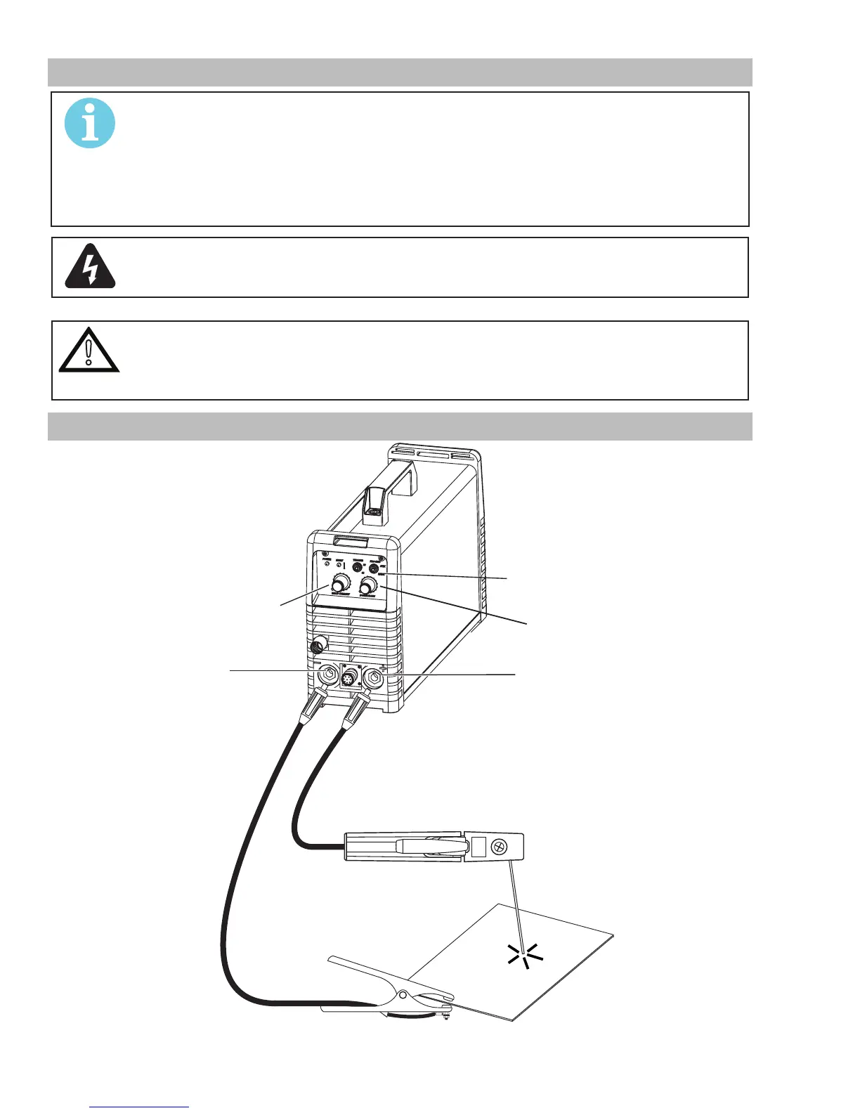
3.06 STICK (SMAW) Setup
200A
elding Current
e
.
Switch to STICK.
Set ARC Force
Positive Output
Terminal
(Dinse™ 50)
Negative Output
Terminal
(Dinse™ 50)
Art#: A-09784
Figure 3-2: Setup for STICK (SMAW) Welding










 To Next Page