ET 201i DC
OPERATION 0-5452
4-8
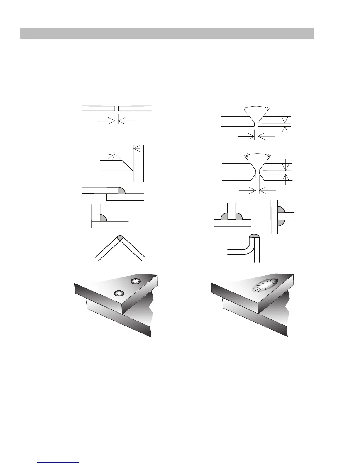
4.14 Joint Preparations
In many cases, it will be possible to weld steel sections without any special preparation. For heavier sections and for
repair work on castings, etc., it will be necessary to cut or grind an angle between the pieces being joined to ensure
proper penetration of the weld metal and to produce sound joints.
In general, surfaces being welded should be clean and free of rust, scale, dirt, grease, etc. Slag should be removed
from oxy-cut surfaces. Typical joint designs are shown in Figure 4-11.
Gap varies from
1/16" (1.6mm) to 3/16" (4.8mm)
depending on plate thickness
Joint
1/16" (1.6mm) ma
1.6mm (1/16”)
Single Vee Butt Joint
Not less than
70°
Double Vee Butt Joint
1/16" (1.6mm)
Lap Joint
Tee Joints
(Fillet both sides of the
joint)
Edge Joint
Fillet Joint
Corner Weld
Plug Weld Plug Weld
Not less than
70°
Single Vee Butt Joint
Not less than
45°
1/16" (1.6mm) max
Art # A-10367
Figure 4-11: Typical joint designs for arc welding



 To Next Page