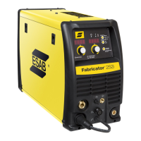
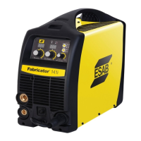
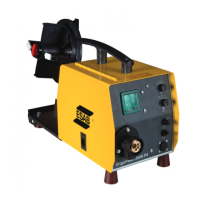
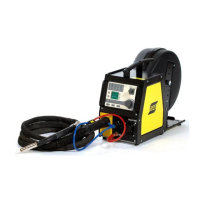
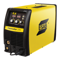
ESAB FABRICATOR 211i
Manual 0-5450 4-5 INSTALLATION/SETUP
When STICK Mode is Selected
In this mode the multifunction control knob is used to adjust arc force. Arc force control provides an adjustable amount of welding
force (or “dig”) control. This feature can be particularly beneficial in providing the operator the ability to compensate for variability
in joint fit-up in certain situations with particular electrodes. In general increasing the arc force control toward ‘10’ (maximum arc
force) allows greater penetration control to be achieved. Arc force is increased by turning the control knob clockwise or decreased
by turning the knob anti-clockwise
When LIFT TIG Mode is Selected
In this mode the multifunction control knob is used to adjust down slope. Down slope allows the user to select the ramp down
time at the completion of the weld. The main function of down slope is to allow the welding current to be gradually reduced over
a pre-set time frame such that the welding pool is given time to cool sufficiently.
Note that when in 2T normal mode (refer item 12), the unit will enter down slope mode as soon as the trigger switch is released
(ie if the multifunction control knob is set to 5, the unit will ramp down from the present welding current to zero over 5 seconds).
If no down slope time is selected then the welding output will cease immediately. If the unit is set to 4T latch mode, to enter down
slope mode the trigger must be held in for the selected time period (ie press and release trigger to commence welding, then press
and hold trigger again to enter down slope mode). Should the trigger be released during the down slope phase (4T only), the output
will cease immediately.
11. Arc Control (Inductance)
The arc control operates in MIG mode only and is used to adjust the intensity of the welding arc. Lower arc control settings make
the arc softer with less weld spatter. Higher arc control settings give a stronger driving arc which can increase weld penetration.
Soft means maximum inductance while Hard means minimum inductance.
12. Trigger Mode Control (MIG and LIFT TIG Mode only)
The trigger mode control is used to switch the functionality of the of the torch trigger between 2T (normal) and 4T (latch mode)
2T (Normal Mode)
In this mode, the torch trigger must remain depressed for the welding output to be active. Press and hold the torch trigger to activate
the power source (weld). Release the torch trigger switch to cease welding.
4T (Latch Mode)
This mode of welding is mainly used for long welding runs to reduce operator fatigue. In this mode the operator can press and
release the torch trigger and the output will remain active. To deactivate the power source, the trigger switch must again be de-
pressed and released, thus eliminating the need for the operator to hold the torch trigger.
Note that when operating in LIFT TIG mode, the power source will remain activated until the selected downslope time has elapsed
(refer Item 10).
13. Process Selection Control
The process selection control is used to select the desired welding mode. Three modes are available, MIG (GMAW/FCAW), LIFT TIG
(GTAW) and STICK (SMAW) modes. Refer to section 4.09 or 4.10 for MIG (GMAW/FCAW) set up details, section 4.12 for LIFT TIG
(GTAW) set-up details or section 4.13 for STICK (SMAW) set-up details.
Note that when the unit is powered off the mode selection control will automatically default to MIG mode. This is necessary so
as to prevent inadvertent arcing should an electrode holder be connected to the unit and mistakenly be in contact with the work
piece during power up.
14. Digital Voltage Meter (Right Digital Display)
MIG Mode
This digital meter is used to display the pre-set (preview) Voltage in MIG mode and actual welding voltage of the power source when
welding. At times of non-welding, the digital meter will display a pre-set (preview) value of Voltage. This value can be adjusted by
varying the Multifunction Control Knob (10).
 Loading...