-- 1 8 --
fzb2d2ea
7 FUNCTION DESCRIPTION (CIRCUIT BOARD)
Serial
buss
7.1 General
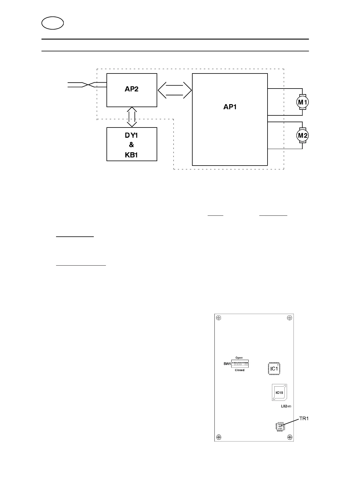
The drive unit consists of two circuit boards, named NME (AP2) and DC DUO (AP1).
(See Page 16 and Page 17 for component positions on the circuit boards.)
The NME board deals with all comm unication with the higher level system via a
two--wire serial bus. It also manages the control panel (KB1) and the display (DY1),
as well as communication with the DC DUO circuit board processor (IC300).
The DC DUO board controls the speed of two DC motors, which may be separately
excited or of permanent magnet type. Speed control is effected either by
measurement of the armature voltage or by tachometer control.
7.2 NME (AP2)
This board is built up around an MC 143150
Neuron processor (IC1), with associated memory,
working memory and program memory (IC15) and
necessary address decoding.
An 8--pole DIP switch (SW1) on the board is
used to set the board’s system addr ess.
As immunity to interference is particularly important,
communication is galvanically isolated through
transformer TR1.
The communication is disconnected by a
single--pole relay, when the board is not powered
but still connected to the system.
Communication with the DC DUO circuit board is via
a parallel bus.
GB