-- 2 5 --
fzb2i1ea
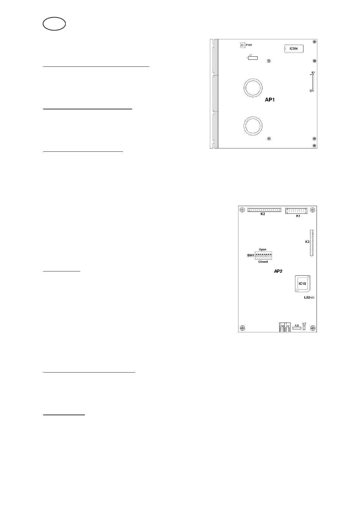
9.4 Adjusting the DC DUO
Adjusting th e display con trast
As delivered, the lighting is set for the
best contrast. If necessary, it can be
adjusted by potentiometer P101
Connection of jumper J1:
For the green display place the jumper on 1 and
2.
For the blue display place the jumper on 2 and 3.
Motor control software
The motor control program is stored in an
EPROM, IC 304. It is marked to show the
version number of the software supplied.
9.5 NME connection
The graphic display is to be connected to connector K1.
The keyboard is to be connected to connector K2.
The bus connection in the control cable (from the
welding power source) is to be connected to
connector K9.
DIP switch
The NME circuit board carries a DlP switch (SW1) which
is preset on delivery for use with A2--A6 units, and its
settings must not be altered in the field. When supplied
as a spare part, the settings of the switch must be
checked, and adjusted if necessary, before the board is
fitted in the control box.
Setting the DIP switch SW1:
DIP s witch SW1 must be set to Closed position,
i.e. all eight poles must be set to Closed position.
Communications software
The communications software, the keyboard controller, display driver and the trim
parameters for the DCDUO circuit board are stor ed in flash memory IC15.
The chip is mounted in a socket and can be changed.
Diagnostics
There is one LED (L02 RED) on the circuit board that can be used for system fault
tracing:
S The LED lights to indicate failure of communication to the DC DUO board, or in
the event of a microprocessor fault.
S The LED flashes to indicate that there is a fault in the program.
GB
 Loading...