Adjusting Base Anti-Backlash
Qualified Technician Only
Refer to the exploded views of the robot in Figures 22 and 23.
1. Refer to Figure 19. Remove the shoulder cover:
•
Remove the top three screws on each side of the shoulder
cover.
•
Loosen (or remove) the bottom screw on each side.
2. Refer to Figure 23. Remove the base lock nut (S286).
3. Refer to Figure 22.
•
Remove the two socket head cap screws (S19), and detach
the base motor from the base plate (12).
•
Check the set screw (S151) that holds the spur gear (S25) to
the base motor gear (S309). If it is loose, tighten it.
•
Reattach the base motor to the base plate.
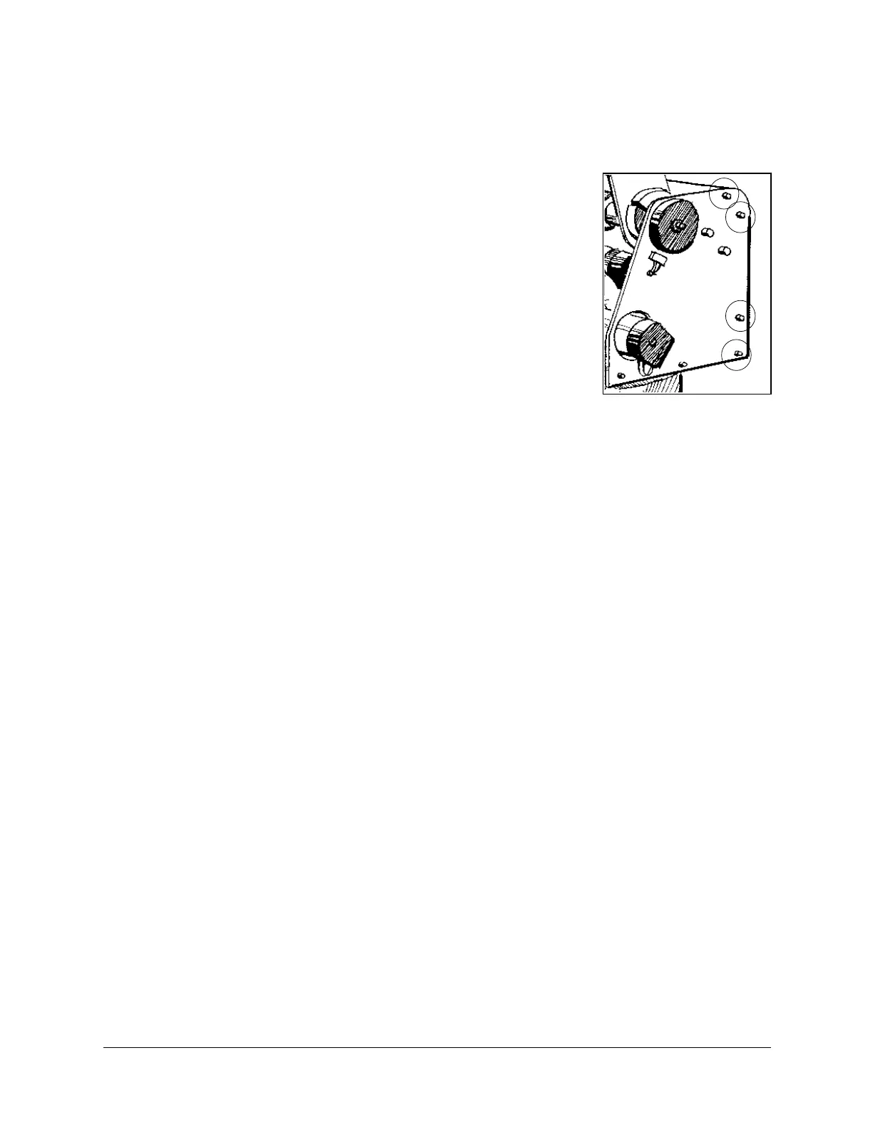
4. Refer to Figure 22. The anti-backlash unit has four gears. Two gears (22 and 27) are on
top of one other with a spring (23) fitted in between. Stretch the anti-backlash spring in
the base transmission:
•
Make sure the robot is bolted in place.
•
Remove the outermost gear (20). The gear (22) is now free. Note the small unused
hole on the base plate near the gears (22 and 27). It will enable you to lock the gear
(22) in the next step.
•
To prevent the gear (22) from moving during the following steps, lock the gear by
inserting a short pin through this hole and into a groove in this gear. Make sure the
pin does not touch the gear (27) and that the gear (27) is free to rotate.
•
Mark the two teeth which are directly above one another on the gears (22 and 27),
one on the upper gear and one on the lower gear.
•
Manually turn the robot counterclockwise a distance of six teeth between the marked
teeth. The spring should now be correctly stretched.
•
Return the gear (20) to its position and fasten the screw.
•
Remove the locking pin.
5. Replace the base lock nut (S286).
6. Replace the shoulder cover.
Figure 19: Shoulder
Cover Screws
SCORBOT-ER 4pc 22 User’s Manual
9810