Single Axis Wiring
In addition to the robot’s six motors, the Controller-PC can control two additional
motors (axes 7 and 8) which operate peripheral devices. These additional motors are
connected to the controller by means of D9 connector ports on the front of the
SCORPOWER box.
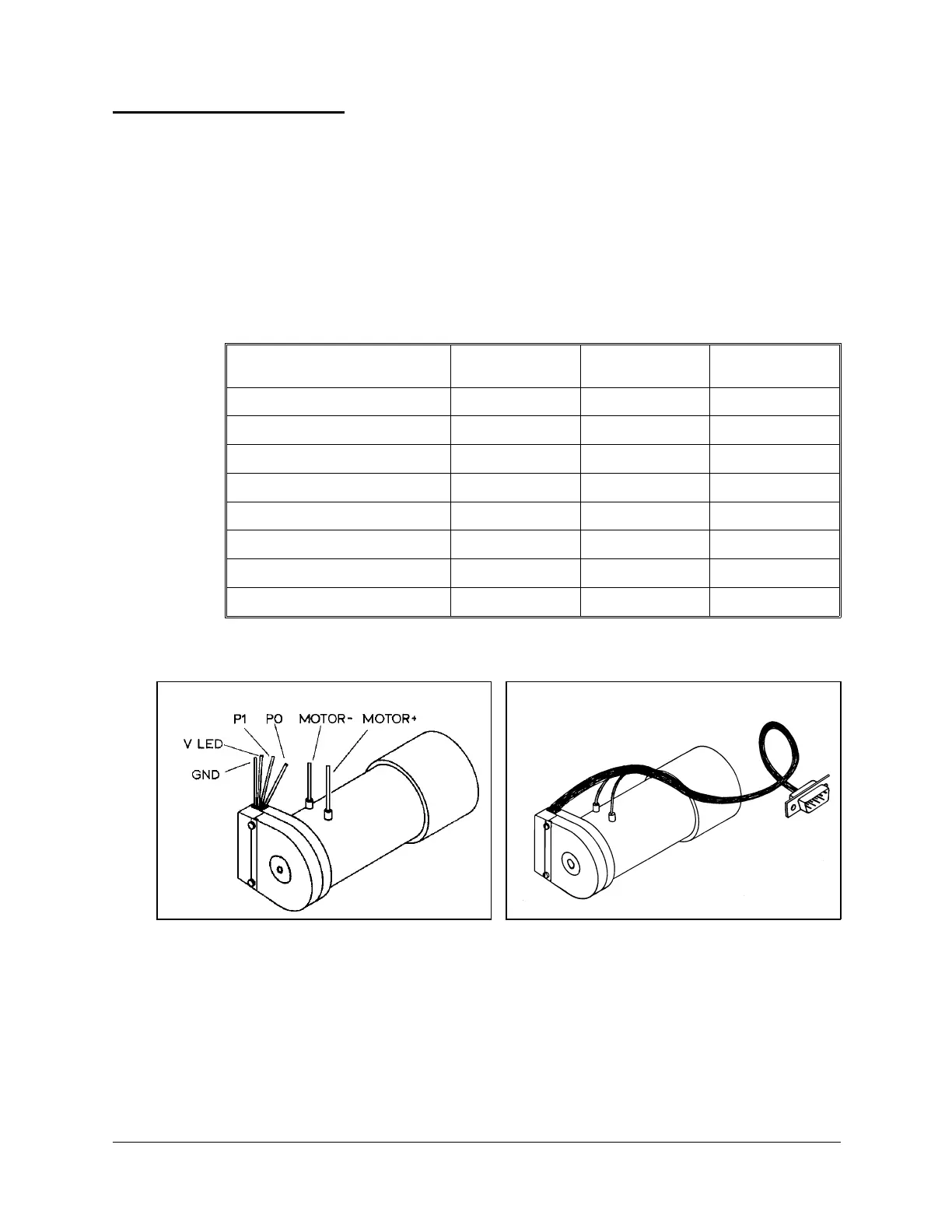
The following table details the wiring for a motor, encoder, and (optional) microswitch
when connected to the controller. Refer to Figures 25 and 26.
The last column in the table shows the colors of the leads used in the Motor Kit accessory.
Function
Encoder
(PC510) Pad #
D9 Connector
Pin #
Motor Kit
Lead Color
Motor Power (+)
1red
Motor Power (–)
9 green
Encoder Phototransistor (P
0
)
4 8 brown
Encoder Phototransistor (P
1
)
36white
Encoder LED voltage (V
LED
)
2 3 yellow
Encoder Ground (GND)
1 5 + Shield black
Microswitch Signal (MS) *
4 orange
Microswitch (GND) *
5 orange
Figure 25: Motor Wiring Figure 26: Motor with D9 Connector
User’s Manual 35 SCORBOT-ER 4pc
9810
 Loading...