CHAPTER
8
Wiring
Robot Wiring
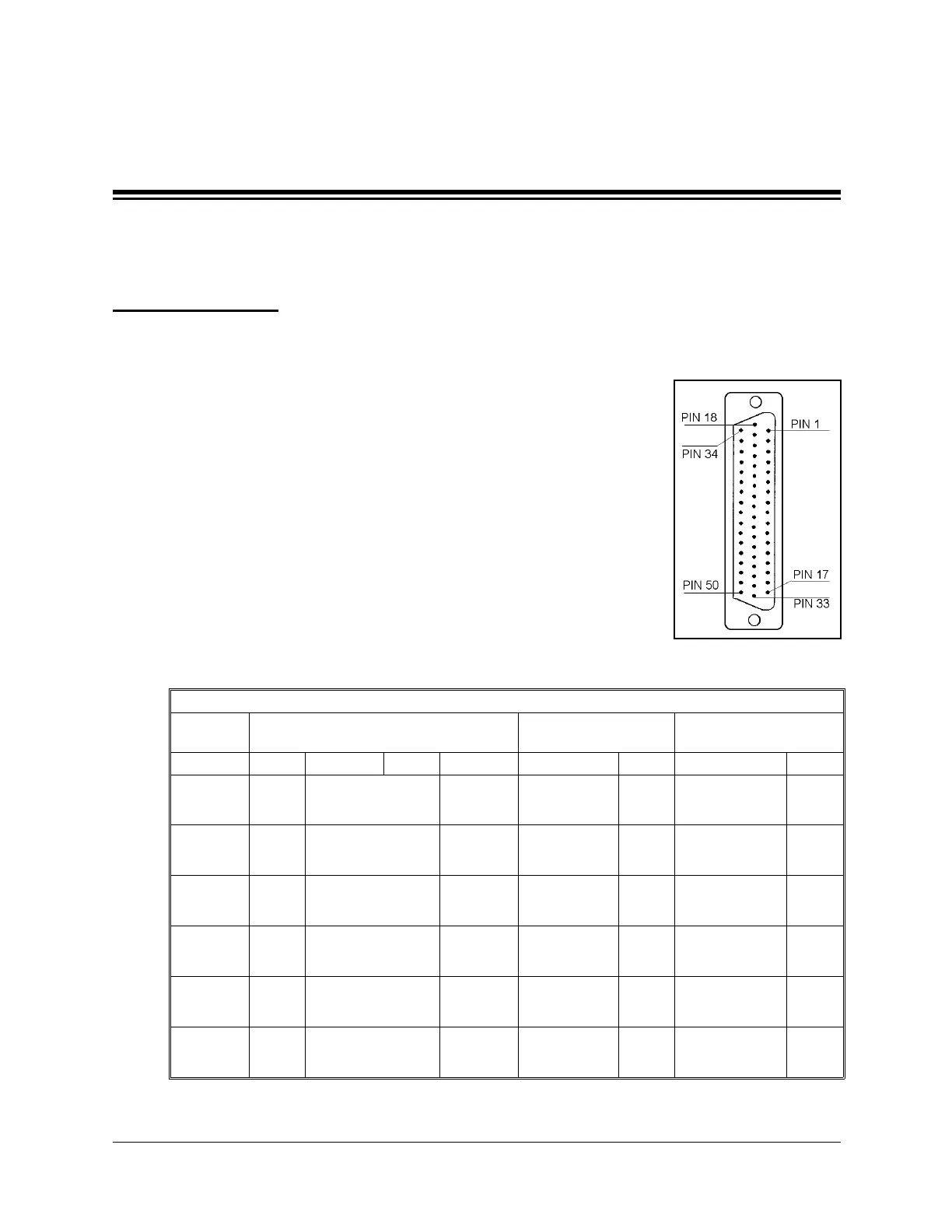
The robot is connected to the Controller-PC by means of a cable
which runs from the robot base to the D50 connector marked
ROBOT
on the rear panel of the SCORPOWER box.
The leads from the five motors on the robot body and their
encoders are connected directly to the D50 connector on the robot
cable. The leads from the gripper motor and the microswitches on
the arm reach the D50 connector via a square 12-pin Molex
connector in the base of the robot; these leads are particularly
flexible and resistant to breakage, even after extensive movement
of the robot arm.
The following table details the wiring for the various electrical
components in the
SCORBOT-ER 4pc
robot.
(* indicates two wires on same pin.)
SCORBOT-ER 4pc Wiring
Robot Arm Signal
Lead to Molex
12-pin Connector
Lead to
D50 Connector
Axis Motor Encoder Pad # Microsw. Color Pin# Color Pin #
1
+
white
50
–
gray/green
17
2
+
white
49
–
white/green
16
3
+
white
48
–
orange/brown
15
4
+
white
47
–
orange/green
14
5
+
white
46
–
orange/gray
13
Gripper
+
gray
8
white
45
–
yellow
7
orange/blue
12
Figure 24:
Robot D50 Connector
User’s Manual 33 SCORBOT-ER 4pc
9810
 Loading...