26 Network Controllers Manual
3 Supervisory Short
4 Sensor Alert
P Internal
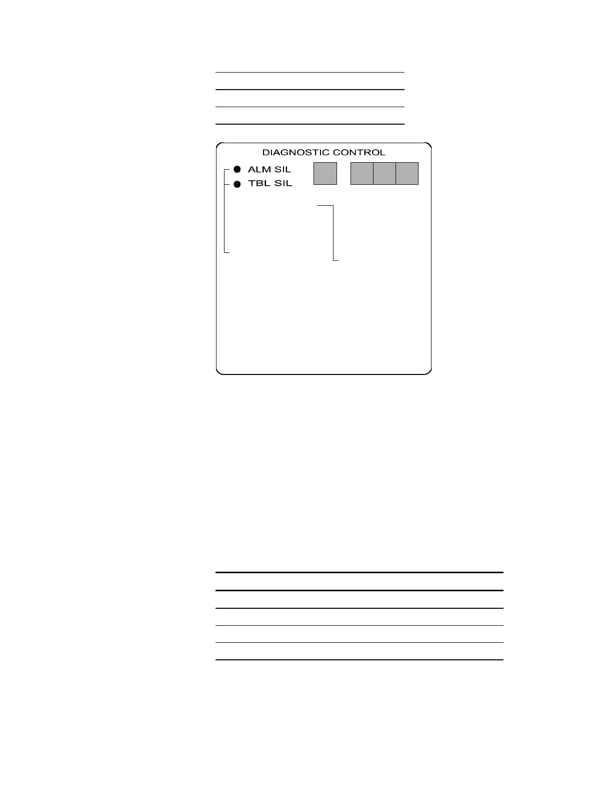
To R E SE T, p us h
both switches
simultaneously
ZONE/DEVICE
1. FIRE ALARM
2. SUP. OPEN
3. SUP SHORT
4. SENSOR ALERT
P. INTERNAL
P 001 = 24 Vdc output #1 or #2 fail
P 002 = Ground fault
P 003 = AC power fail
P 004 = PS Internal voltage trouble
P 005 = Battery or charger trouble
P 006 = City box/Mic trouble
P 007 = ZAS card fail/continuity
P 008 = Printer fail
P 009 = Alarm Silence
P 010 = Trouble Silence
P 011 = Communications fail
CODE
[NWC-010.CDR]
The "Zone/Device" window indicates the panel address of the
condition. To interpret the "Zone/Device" display when the "CODE"
window displays a 0, 1, 2, or 3, you must know which cards are
installed in the CM2N:
1. Use Table 1 on next page when two ZAS cards are installed in the
CM2N.
2. Use Table 2 on next page when a ZAS card is installed in the top
slot and a traditional card is installed in the bottom slot of the
CM2N.
3. Use Table 3 on next page when two Traditional cards are installed
in the CM2N.
CM2N Display Codes with Two ZAS Cards Installed
Zone/Device Display Code Affected Devices
001 - 096 Top ZAS Card Sensors
101 - 196 Top ZAS Card Modules
201 - 296 Bottom ZAS Card Sensors
301 - 396 Bottom ZAS Card Modules