48 Network Controllers Manual
Theory Of Operation
The 20 mA current loop format transfers information using changes in
current flow rather than voltage levels to indicate logic states. Logic
levels are represented by current flow, and absence of current flow.
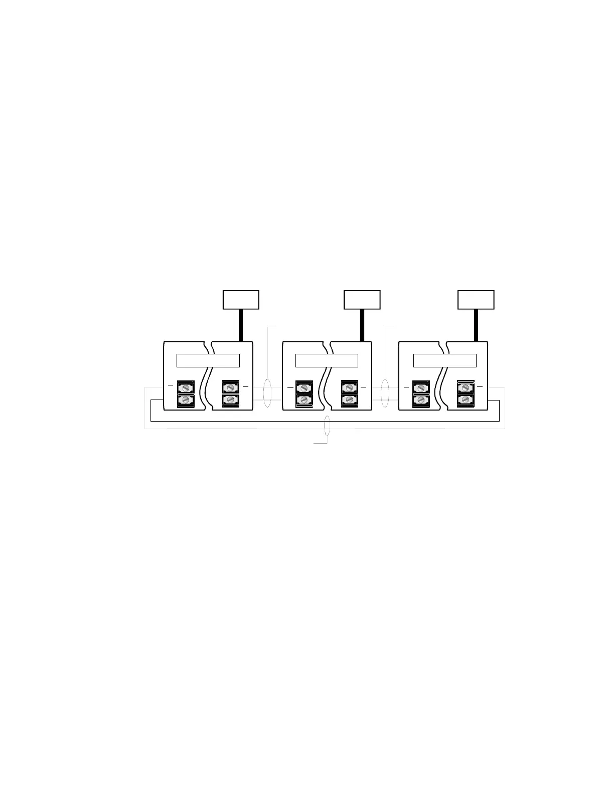
A loop circuit is formed between each pair of SO-20 modules. Three
loop circuits are shown in the figure below, loops A/B, B/C and C/A.
Data is sent by the transmit circuitry (data out terminals) of the SO-20
to the receiver circuitry (data in terminals) of the next SO-20. SO-20
modules act as signal repeaters, regenerating the signal and passing it
along to the next SO-20; with the output of the "last" module looped
back to the input of the "first" module. An open circuit anywhere in the
loop halts all network communications.
The 20 mA current loop is ideal for use with existing 24/26 AWG
twisted pair telephone wire. The constant current source in an SO-20
can compensate for intermodule loop resistance of 400Ω.
TB1
DATA
IN
+
TB1
DATA
IN
+
TB1
DATA
IN
+
TB3
DATA
OUT
+
TB3
DATA
OUT
+
TB3
DATA
OUT
+
[NWC-020.CDR]
CM1N
A/B LOOP
AL
P
B/C LOOP
CM2N CM2N
SO-20 A SO-20 B SO-20 C
Typical 20mA Current Loop