Network Controllers Manual 35
Jumper Connections:
Pins 6, 8, and 20
Pins 4 and 5
Jumper Connections:
Pins 1, 4, and 6
Pins 7 and 8
TB1-2
TB1-2
TB1-3
TB1-3
TB1-4
TB1-4
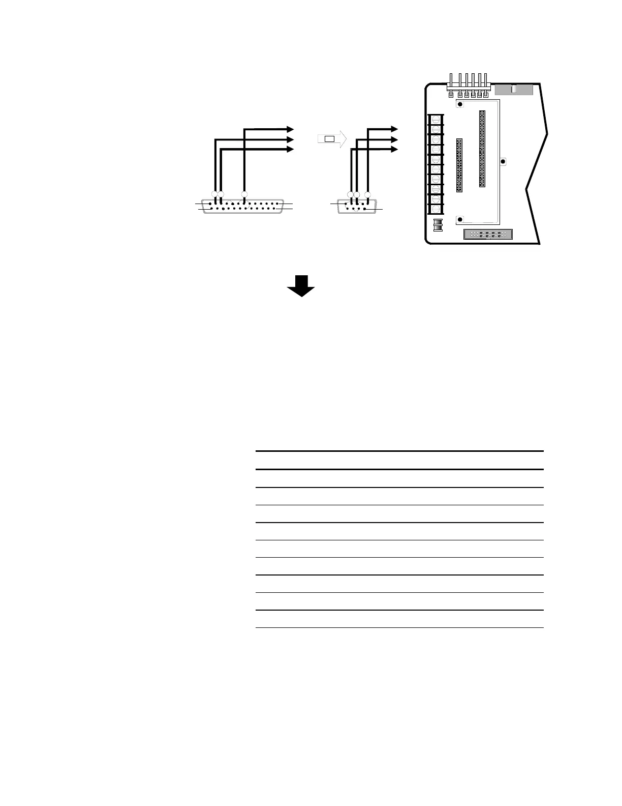
[NWC-004.CDR]
DB25 FEMALE or DB9 FEMALE
Download Cable
T
P
ERIAL P
RT
PIN 1
PIN 14
PIN 13
PIN 25
PIN 1
PIN 9
2
3 7
OR
2
3 5
CONTROL PANEL
MOTHER BOARD CM1(N) or CM2(N
TB1
4
8
10
1
5
3
7
9
2
6
P1
P2
P3
P4
P7
CM2ND Programming Connections
Troubleshooting
The CM2ND displays trouble codes similar to the CM1N. Power
supply faults are indicated by the following letter codes which are
displayed to the right of the active points (AP) counter.
CM2ND Fault Codes
Code Condition
F Fuse Failure
A AC Power Failure
G Ground Fault
B Battery Fault
V Secondary Voltage Fault
E External Trouble
I Internal Fault or Continuity
P Printer Failure
C CM1N Communications Failure