Network Controllers Manual 1
CM1 Master Control Module
Applicable Modules and Options
This manual covers the following modules/options:
CM1 - (P/N 240102) CM1-SO - (P/N - 240185)
CM1-SG - (P/N 240525) CM1-SO-SG - (P/N 240547)
CM1-RM - (P/N 240359) CM1-SO-RM - (P/N 240350)
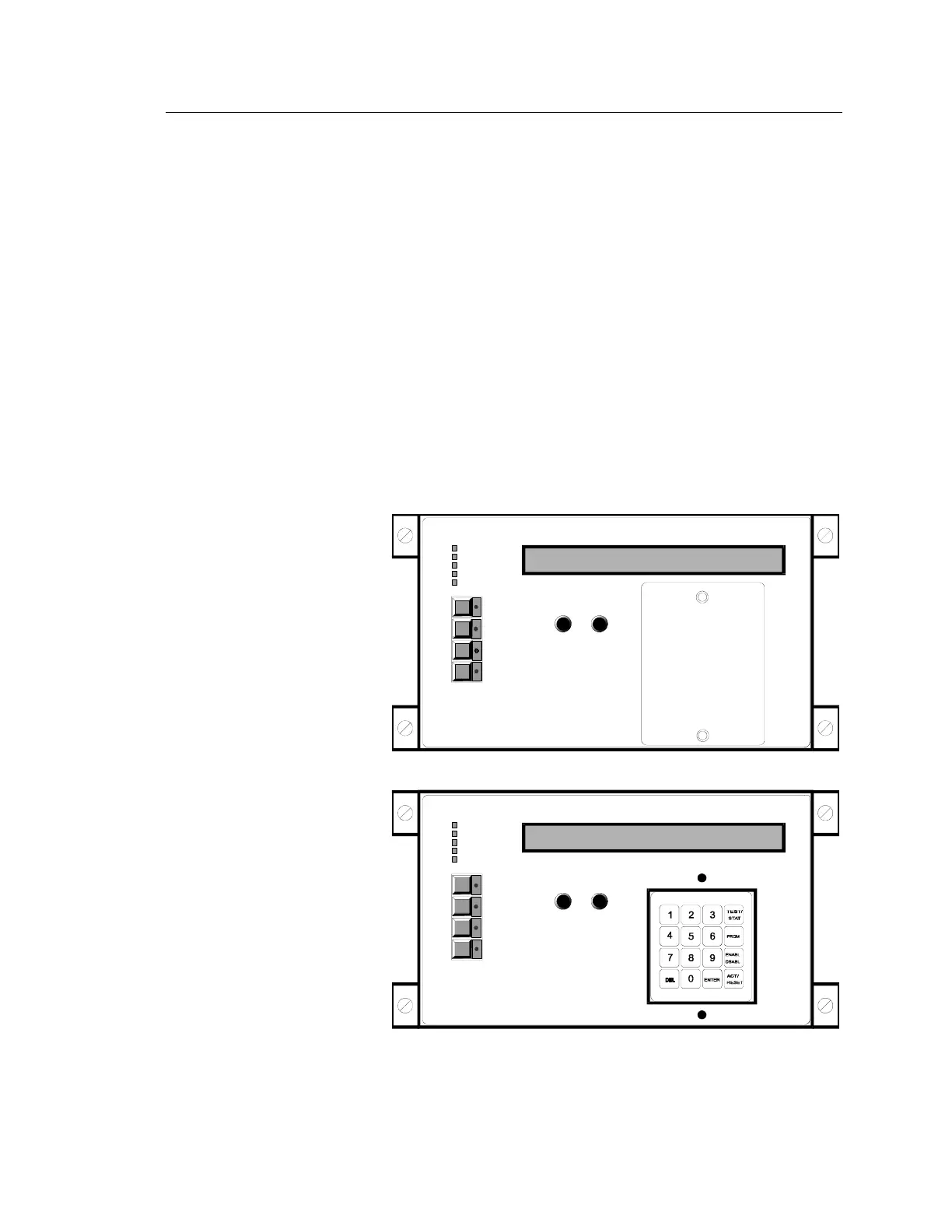
Description
The CM1 is the master controller for a 576 point non-networked
system. This controller contains all the circuitry, memory, instructions,
and controls to define a system. The CM1 incorporates a 2 line, 40
character alpha-numeric LCD display, a keypad for manual control,
LED status indicators, and panel control switches.
OPERATING INSTRUCTIONS
NORMAL
NORMAL
ALARM
ALARM
SUPERVISORY
SUPERVISORY
TROUBLE
TROUBLE
TROUBLE
SILENCE
TROUBLE
SILENCE
MODEL CM1
MODEL CM1
CONTROL MODULE
CONTROL MODULE
BACK
BACK
TEST/PRGM
TEST/PRGM
RESET
RESET
ALARM
SILENCE
ALARM
SILENCE
STATUS AND PROGRAM DISPLAY
STATUS AND PROGRAM DISPLAY
NEXT/ACK
NEXT/ACK
DRILL/
ALL CALL
DRILL/
ALL CALL
NEXT/ACK-Acknowledges
currently displayed
off-normal condition,
then displays next
off-normal condition.
BACK- Reviews previously
acknowledged off-normal
condition.
LAMP TEST- Press ALARM
SILENCE and TROUBLE
SILENCE switches at
the same time.
Keypad under cover
(shown with keypad protective cover installed)
shownwithke
pad p
otective cove
emoved
[NWC-001.CDR]
Model CM1