Network Controllers Manual 41
Application Drawings
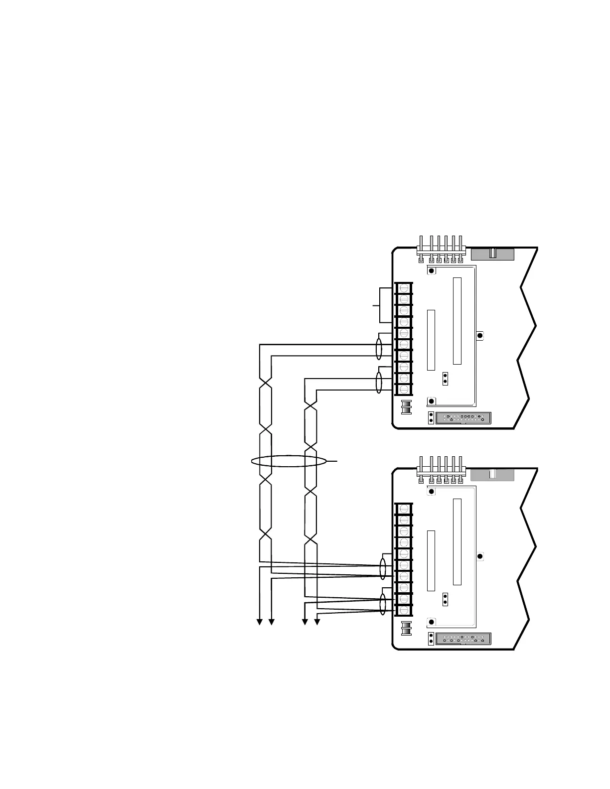
The following diagram illustrates Style 7 (Class A) RS-485 network
signal (data) line wiring between a CM1(N) and CM2(N) control
modules. Both the CM1(N) and the CM2(N) must be equipped with a
COMM-3 communications card in connector P3.
Route data 1 and data 2 cables separately such that a single incident
e.g. fire or accidental cutting will not damage (shorted or open
conductors) both cables. Riser cables should be separated by 2 hour
rated fire resistive construction or a minimum of 20’.
NWC-016.CDR
CM1(N)
NETWORK
MASTER
TB1
4
8
10
1
5
3
7
9
2
6
P1
P2
P3
P4
P7
J1
J2
COMM-3 CARD
CPU CARD
CM2(N)
NETWORK
SLAVE
TB1
4
8
10
1
5
3
7
9
2
6
P1
P2
P3
P4
P7
J1
J2
COMM-3 CARD
CPU CARD
RS-232
SUPERVISED
TO ADDITIONAL FIELD PANELS
DATA 2 (-)
DATA 2 (-)
DATA 2 (+)
DATA 2 (+)
DATA 1 (-)
DATA 1 (-)
DATA 1 (+)
DATA 1 (+)