54 Network Controllers Manual
SO-20D Dual Serial Option to 20mA Loop Module
Description
The SO-20D Dual Serial Option to 20 mA Loop Module, when used in
conjunction with the COMM-3S serial communications card, connects
network components via two independent 20 mA communications
loops. 20 mA communications loops are suitable for long distance use
where 22 to 26 gauge telephone wiring is available. This supervised
network communications loop is configured as a class A (Style 7) loop,
and is capable of communications rates up to 9600 Baud, depending on
line length and installation.
Six red LEDs indicate communication activity on the data out (send)
and data in (receive) lines. Communications failure is annunciated via
the network. Bypass mode lets signals pass through the module in the
event of power loss. This insures network integrity in the event a field
panel should experience a power failure and lose battery backup.
The SO-20D circuitry is protected from line surges and voltage spikes
by integral on board protection devices.
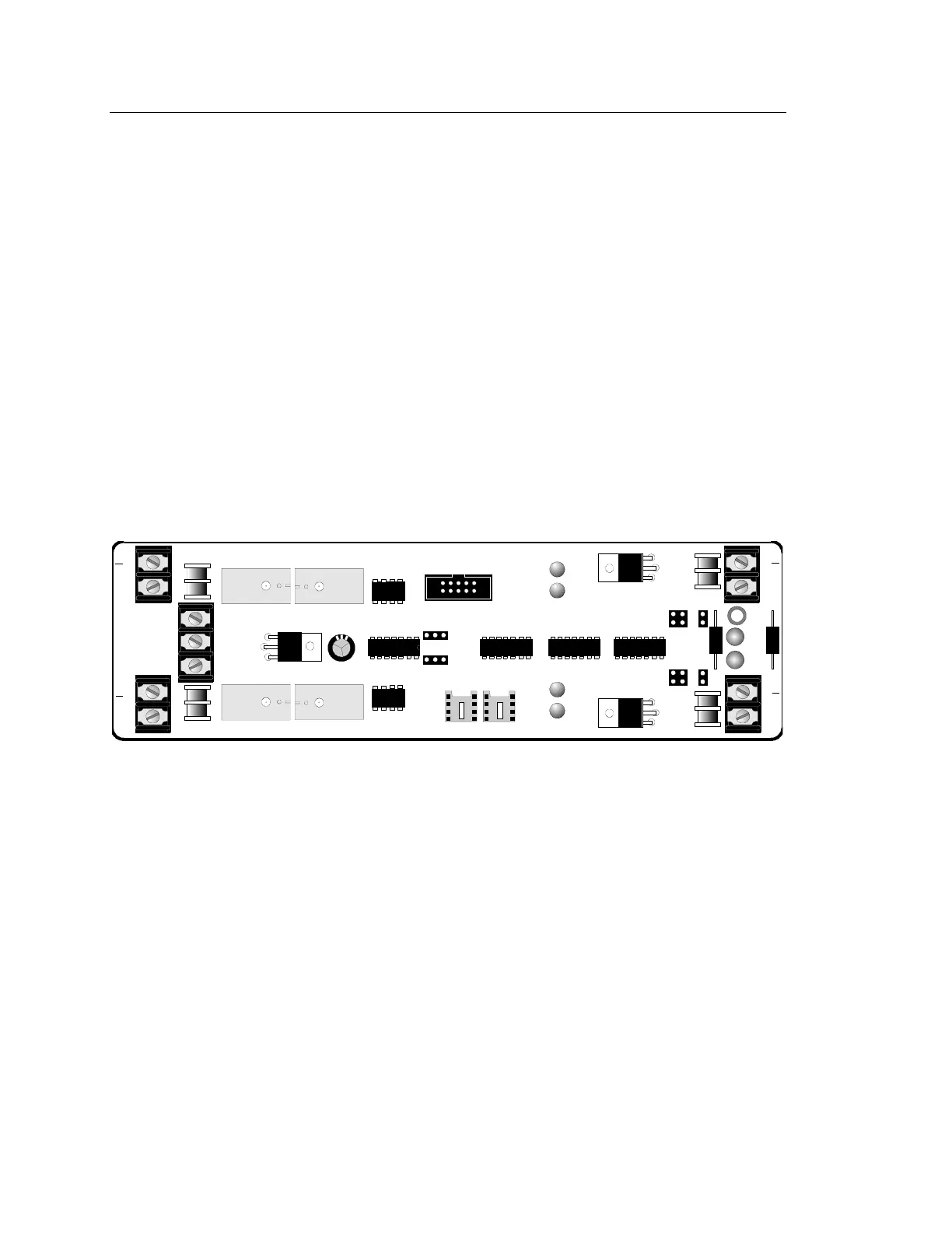
LD6
LD4
LD5
P1
P2P3
JP8
JP3
JP7
JP2
TB2
TB4
TB3
TB1
TB5
EARTH
COM
+24V
JP5
JP10
LD1
LD2
+
+
+
+
CH1 OUT
CH1 IN
CH2 IN
CH2 OUT
LD3
[NWC-026.CDR]
SO-20D Module
The SO-20D module connects to the CM1(N) with SO Option, the
RMDP-1N w/SO Option, and the CM2(N) w/SO Option using a 10
conductor ribbon cable (P/N 250099) which terminates on the COMM-
3S Serial Communications Card (P/N 130144). The COMM-3S card
plugs into control module mother board communications slot P3. When
an COMM-3S card is used, the RS-232C signal is available on control
module mother board terminals TB1-1 to TB1-4.
The SAN and RASP annunciators (via the SAN CPU and REM cards
respectively); and the IRC-1 may be connected to the IRC-3 network
with a 20 mA loop. When 20mA loop communication is used to
network these components, their RS-485 communications driver chip is
removed from its socket. In its place, an 8 pin header and ribbon cable
(P/N 250098) is inserted, and connected to the SO-20 at P3.
Note: Regenerative network capability is not compatible with COMM-
3S card communication (20mA Loop and Fiber Optic Link) protocol.