32 Network Controllers Manual
[NWC-012.CDR]
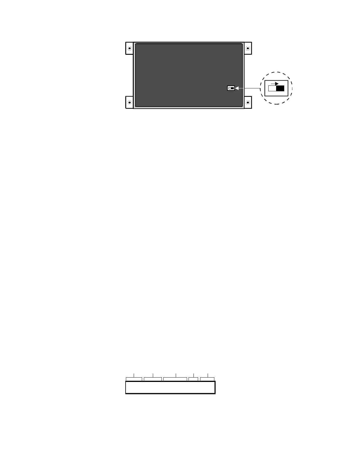
INSIDE BACK COVER
OF CM2ND
ON
CM2ND, Rear View of DIP Switch
Note:
Switches shown in program mode. All Switches off for normal
operation.
Indicators
LEDs
Normal - Green LED indicates CM2ND is normal, i.e. no zone alarms,
troubles or internal faults.
Alarm - Red flashing LED indicates the Network has detected an alarm
condition.
Supervisory - Yellow flashing LED indicates CM2ND has detected a
local supervisory condition.
Trouble - Yellow flashing LED indicates the CM2ND has detected a
local trouble condition.
CM2ND CPU status is indicated by the CPU Fail LED on the
associated power supply.
CM2ND communication status is indicated by LED's on the
communications cards.
Alphanumeric LCD Display
Two Line 40 character liquid crystal display indicates off-normal
conditions and CM2ND status. The display on the CM2ND/RM rack
mount version is backlit.
08:53:18 MW 0000 FIRE ALARM 0503
P
R
E
S
E
N
T
T
I
M
E
#
O
F
M
E
S
S
A
G
E
S
W
A
I
T
I
N
M
E
S
S
A
G
E
T
Y
P
E
P
O
I
N
T
I
D
E
N
T
I
F
I
C
A
T
I
O
N
E
VE
N
T
TI
M
E
40 CHARACTER CUSTOM MESSAGE
@08:51
[NWC-013.CDR]
Typical CM2ND Display