Network Controllers Manual 25
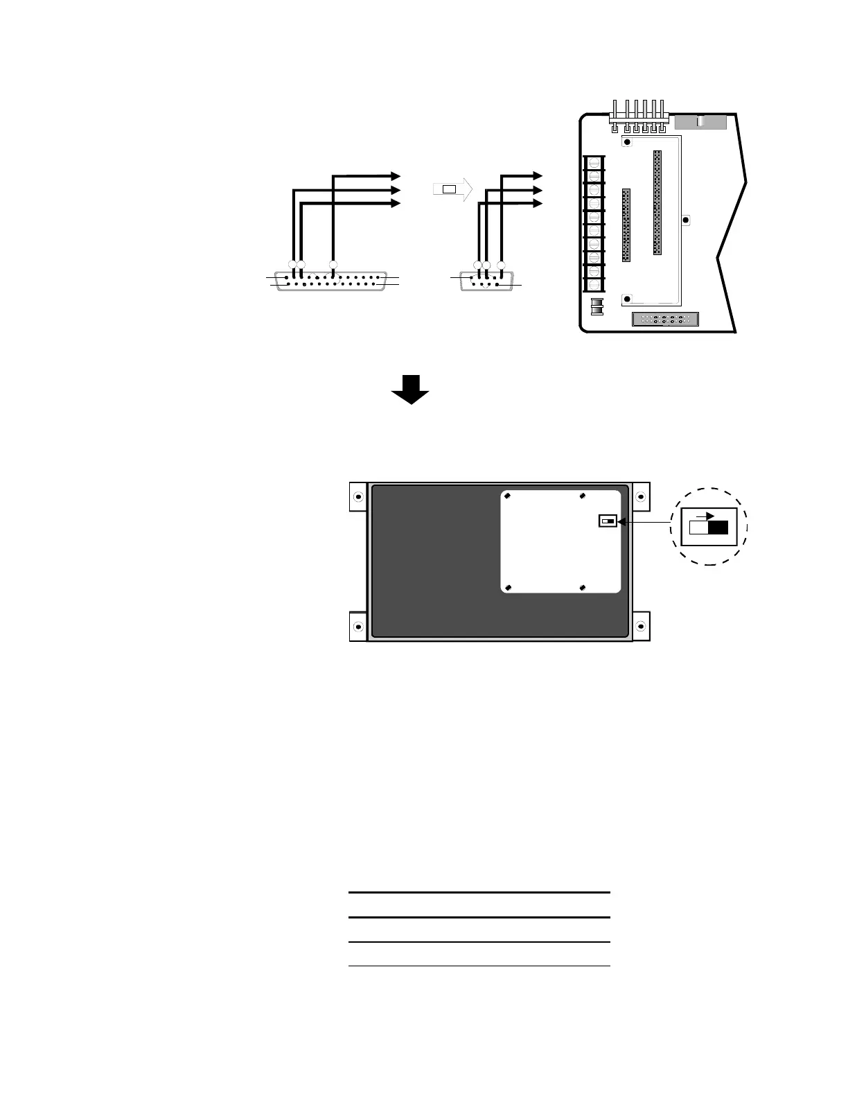
Jumper Connections:
Pins 6, 8, and 20
Pins 4 and 5
Jumper Connections:
Pins 1, 4, and 6
Pins 7 and 8
TB1-2
TB1-2
TB1-3
TB1-3
TB1-4
TB1-4
[NWC-004.CDR]
DB25 FEMALE or DB9 FEMALE
Download Cable
T
P
ERIAL P
RT
PIN 1
PIN 14
PIN 13
PIN 25
PIN 1
PIN 9
2
3 7
OR
2
3 5
CONTROL PANEL
MOTHER BOARD CM1(N) or CM2(N
TB1
4
8
10
1
5
3
7
9
2
6
P1
P2
P3
P4
P7
Programming Connections
[CCM2NDI P.CDR]
INSIDE BACK COVER
OF CM2N
CM2N
DISPLAY CARD
(REAR VIEW)
ON
DIP Switch Position on CM2N
Note:
Switch shown in program mode (on). Switch “off” for normal
operation.
Troubleshooting
The CM2N front panel seven segment LED displays are divided into
two windows. The readout in the "CODE" window indicates the nature
of the alarm as indicated in the table below.
CM2N Display Codes
Code Description
1 Fire Alarm
2 Supervisory Open