Network Controllers Manual 59
FIB-20 Serial Option 20mA Loop Card, SO-FIB Option
Fiber Optics Interface Module
Description
The SO-FIB Serial Option to Fiber Optics Module connects network
components via fiber optic cables. This supervised network
communications link is capable of communications rates up to 9600
Baud, and may be installed in Class A (Style 7) [with two modules] or
Class B (Style 4) configurations. A maximum of 10 modules may be
installed on a loop. Each communication loop consists of TWO fiber
optic cables.
Two red LEDs verify communications on these send and receive lines.
An integral standby battery and charger insures continued network
communications in the event of AC power and primary battery backup
loss. This feature facilitates servicing local panels without interrupting
network communications.
When a class A fiber optic network is required, a second SO-FIB
module is installed by paralleling power and trouble wiring, and
connecting a 10 conductor ribbon cable (P/N 250099) between P2 of
the first board to P1 of the additional SO-FIB board.
The FIB-20 module is a daughter board to the SO-FIB board and
creates a 20 mA. communications sub-loop. This is useful for inter
cabinet wiring, eliminating the need for more expensive fiber "wiring"
within cabinets or buildings. The FIB-20 circuitry is protected from
line surges and voltage spikes by integral on board protection devices.
Note: The SO-FIB connected to the CM1N does NOT support FIB-20
sub loop operation.
Network communications speed may be lowered when long distance
20mA communications loops are used on the network. The speed
reduction is dependent on the loop installation, and speed reduction is
unique for each installation.
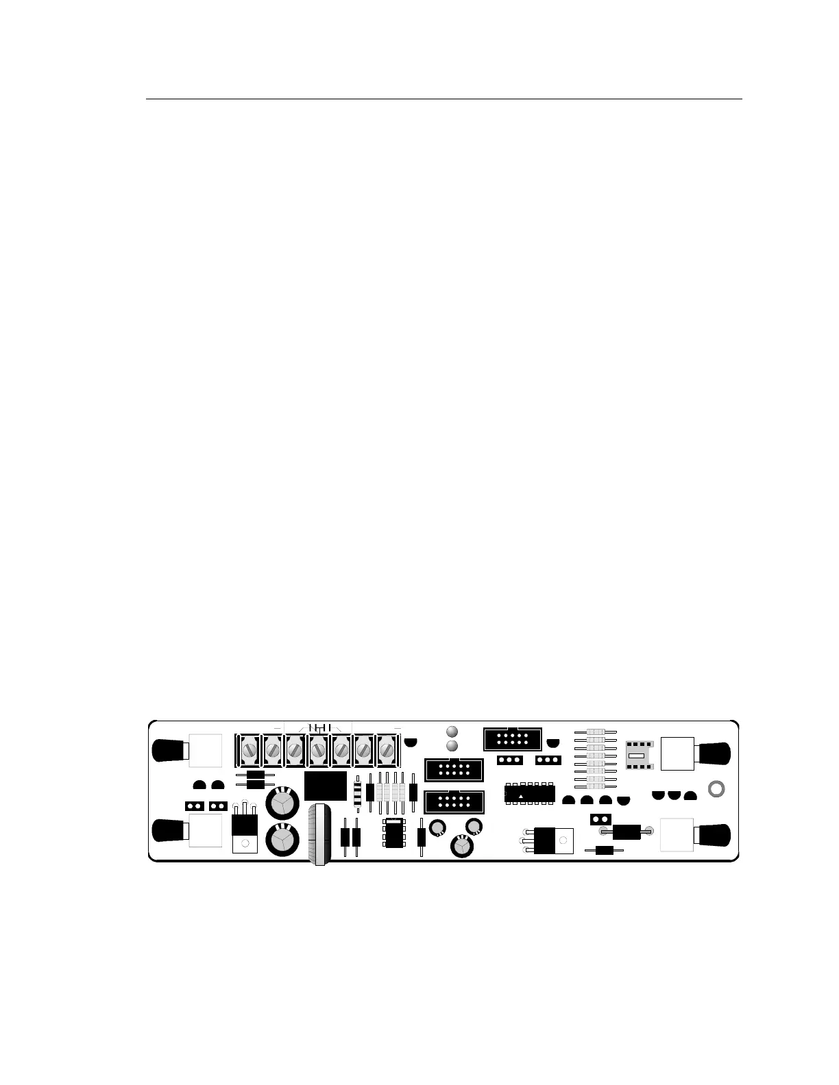
UCN 5800A
9111
TB1FONC 1
FONC 4 FONC 3
FONC 2
JP3
JP1
RXD
IN
TXD
OUT
TXD
OUT
RXD
IN
JP2
P1
LD1
LD2
P2
P3
JP4
JP5
24V IN 12V BAT
PWR TBL
++
MAXIM
[NWC-030.CDR]
SO-FIB Module