23
EN
1
2
3
4
5
6
7
8
9
10
5.9 OMNIBUS DIGITAL CONTROL
The OMNIBUS digital control system permits a complete and integrated management of several fancoil units installed in the
same building. It is designed either for a stand-alone operating mode, or to be integrated, at different levels, to a centralized
Building Automation System, with a serial communication protocol RS-485 (Modbus RTU).
The digital regulator can control many fancoils at the same time (Master/Slave solution), which are connected together by two
twisted wires (AWG 24).
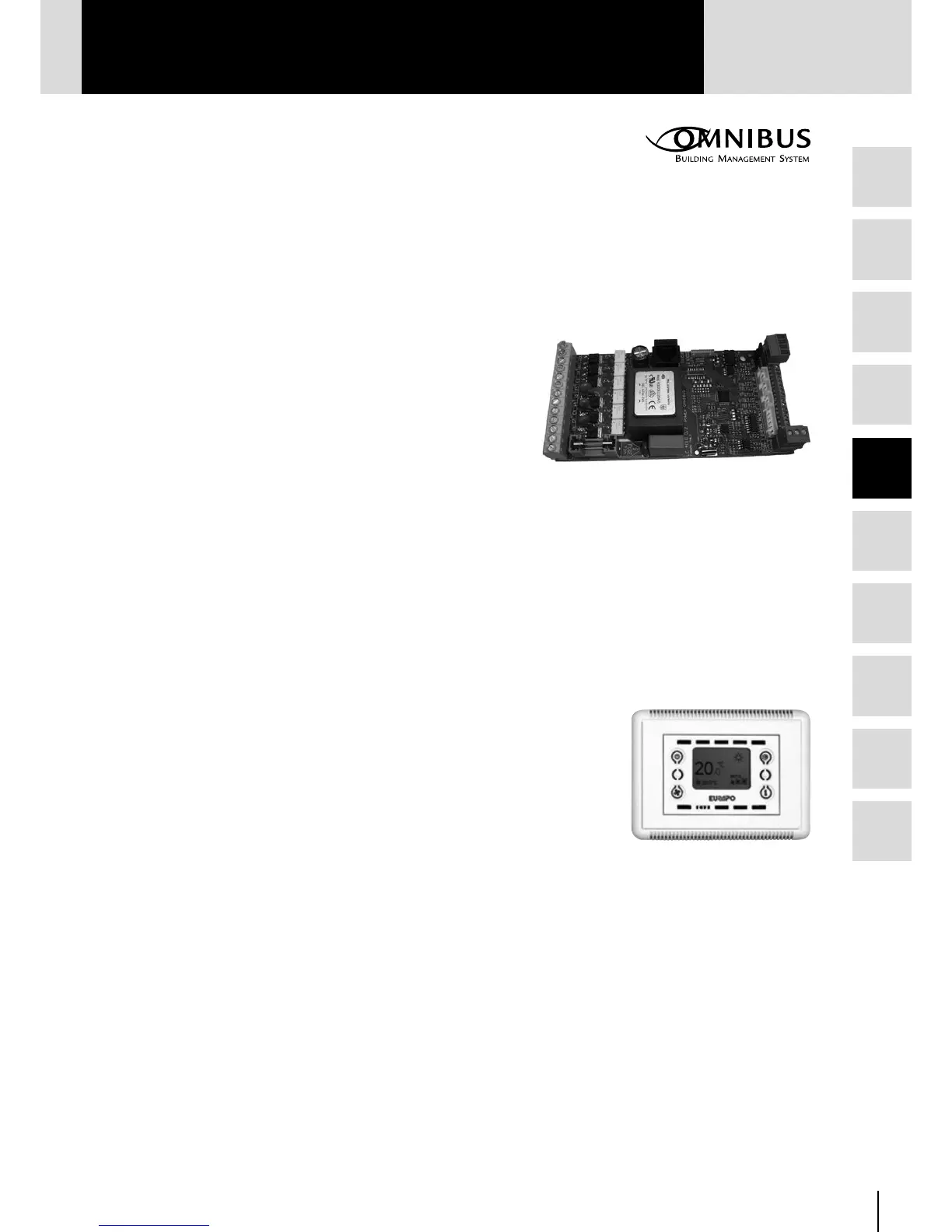
5.9.1 POWER OMNIBUS CARD for BMS – OPV10
The Power Omnibus card mounted on the unit is designed to fully
regulate (directly or via Modbus) the water terminal units.
The card can provide:
• 6 ON/OFF outputs: Fan speed Minimum-Medium-Maximum;
Electric heater/Dehumidification; Hot water valve, Cold water valve
• 3 Analogue 0-10V ouputs: Heating modulating valve, Cooling
modulating valve, Auxiliary fan
• 5 Outputs on the additional multitask card OPV50: On/off heating
valve 24V; On/off cooling valve 24V; Auxiliary fan for fresh air and/or free cooling; Alarm contact; External air damper
• 5 Analogue inputs: Room temperature sensor (AS), Water sensor (WS), Air outlet sensor (CS), External air temperature
sensor and relative humidity sensor
• 3 Digital inputs: Economy contact; Window contact; contact for the thermal protection of the motor
• 2 Serial communication ports (RS485): Network “Local Bus” for the connection of the Console (built-in the unit or for
remote installation); Network Modbus for the connection of the Manager Console or other Supervision System (BMS)
This card is available also without BMS communication (ONV10).
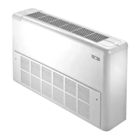
5.9.2 DISPLAY CONSOLE - OC236
The Console is connected to the Power Omnibus card by a phone cable (4 wires), from
which it is energized (15 Vcc) and it receives information from the Local-bus network.
The Display Console is provided with four buttons for setting the parameters and the
operating modes of the water terminal unit:
• Status: OFF-Comfort-Economy
• Fan: Low, Med, High, Auto
• Mode: Cool-Heat-Fan-Dry
• Room temperature Set-point
The Display Console can be used as “service tool”:
• identification by code of possible alarms
• setting or variation of the Modbus address
• visualization of the I/O status
OC236
OPV10