Schematic Diagrams
B-1
Schematic Diagrams
Appendix B:Schematic Diagrams
This appendix has circuit diagrams of the systems PCB’s.
Printed Circuit Board Part No. of the Latest Version
System Board 71-M2200-D06
Inverter Board 71-M220R-D03
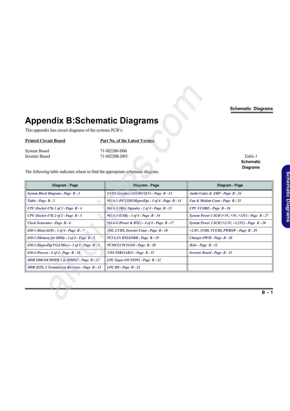
The following table indicates where to find the appropriate schematic diagram.
Table 1
Schematic
Diagrams
Diagram - Page Diagram - Page Diagram - Page
System Block Diagram - Page B - 2 LVDS Interface (SiS301/2LV) - Page B - 13 Audio Codec & AMP - Page B - 24
Table - Page B - 3 961A-1 (PCI/IDE/HyperZip) - 1 of 4 - Page B - 14 Fan & Modem Conn - Page B - 25
CPU (Socket 478) 1 of 2 - Page B - 4 961A-2 (Misc Signals) - 2 of 4 - Page B - 15 CPU VCORE - Page B - 26
CPU (Socket 478) 2 of 2 - Page B - 5 961A-3 (USB) - 3 of 4 - Page B - 16 System Power 1 SCH (+3V, +5V, +12V) - Page B - 27
Clock Generator - Page B - 6 961A-4 (Power & RTC) - 4 of 4 - Page B - 17 System Power 2 SCH (+2.5V, +1.25V) - Page B - 28
650-1 (Host/AGP) - 1 of 4 - Page B - 7 IDE, LVDS, Inverter Conn - Page B - 18 +1.8V, 3VH8, VCCID, PWRSW - Page B - 29
650-2 (Memory for DDR) - 2 of 4 - Page B - 8 PCI LAN RTL8100B - Page B - 19 Charger-PWM - Page B - 30
650-3 (HyperZip/VGA/Misc) - 3 of 4 - Page B - 9 PCMCIA PCI1410 - Page B - 20 Hole - Page B - 31
650-4 (Power) - 4 of 4 - Page B - 10 1394 TSB43AB21 - Page B - 21 Inverter Board - Page B - 32
DDR SDRAM DIMM 1 & DIMM2 - Page B - 11 LPC Super I/O NS393 - Page B - 22
DDR SSTL-2 Termination Resistors - Page B - 12 LPC H8 - Page B - 23