Euroscan MX1 6
Document number: EN-301-1:UD - based on Firmware version 1.033 and forward
2.4 Cabling
The installation set of the Euroscan – recorder contains almost all components required for a standard installation
with two temperature sensors. In addition to that, some small materials like a silicon kit, PVC trunking, and fixing
materials for cable mounting are required.
Preferably, use for both outside and inside bulkheads, the existing cable trunking. Alternatively, use self
adhesive cable trunking. All drilled holes need to be sealed with a suitable sealant.
For future calibration requirements, it is advisable to allow enough spare cable to enable the sensor to be
lowered to the floor.
2.5 Connectors
As both versions are provided with identical PCBs, the connections for temperature sensors, digital inputs and
power supply are the same for both versions. On the main PCB you will find two connector blocks for power,
RS232 and input/output (see picture). If a temperature module is installed another two connector blocks will be
available for connecting analog and digital inputs. Each connector is described in detail in the next paragraphs.
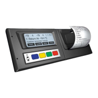
An overview-picture of the recorder can be found on the next page.
Connector block 1 (power supply and outputs)
Connect power supply on pin 1 (+) and pin 2 (-). The recorder is suitable for a voltage between 10 and 36 volts
DC. Pin 3 is digital in, pin 4 is digital out.
Connector block 2 (serial port)
The temperature recorder has two serial communication ports. These are used for a permanent connection with
external devices. To be connected with a suitable connector (connector block 5-way, P/N ET-0300-15).
Connector block 3 (temperature inputs)
Euroscan recorders offer the possibility to connect up to 4 temperature sensors. Pins 1-8 are accordingly marked
with T1-T4 (T1 = Pins 1+2, ...). Pins 2, 4, 6, and 8 are signal inputs and pins 1, 3, 5, and 7 are internally
connected to ground. The polarity of the sensor cable is not relevant. In the factory settings inputs 1 and 2 are
activated and pre-programmed as follows: T1 = return air, T2 = rear. Please note that a used input always has to
be activated and configured via EuroTOOL or equivalent (see paragraph 2.7).
Connector block 4 (digital inputs)
Euroscan-recorders offer the possibility to connect up to 4 digital inputs. Pins 1-8 are accordingly marked with
D1-D4 (D1=Pins 1+2, ...). At every opening or closing of the input circuit a status change will be recorded into
memory, but only if the input has been activated and configured correctly in the parameter settings. All four inputs
as standard are de-activated, the next functions are pre-programmed: D1 = refrigeration, D2 = back door, D3 =
defrost, D4 = side door. For the status inputs the polarity must be considered. Pins 2, 4, 6, and 8 are internally
connected to ground. Pins 1, 3, 5, and 7 are signal inputs.