Any dierent conguration than the
ones presented above is considered in-
valid and causes an error state.
Install and congure either CT coils or
HEMS, not both. If both are installed
and congured, only the lower current
setting gets applied.
The wallbox will not detect a ground
connection if the ground loss monitoring
functionality is disabled.
Set the CT coil's parameters locally using
the Configuration Manager of the wallbox.
See chapter Configure the Audi Wallbox
plus and Audi Wallbox pro locally for more
information.
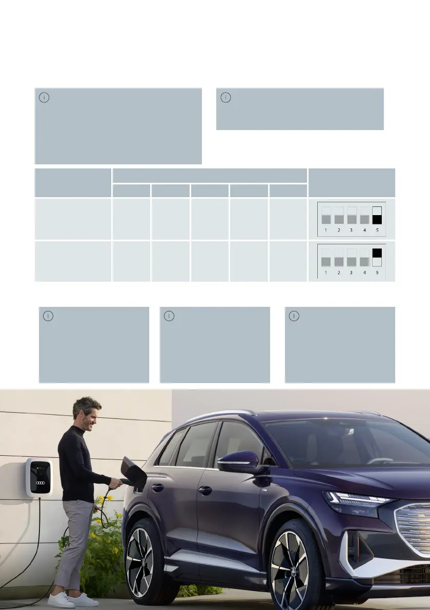
Ground loss monitor configuration
DIP-switch 5, in group A configures the functio-
nality of the ground loss monitor. By default,
this feature is enabled from the factory.
Group A switches
Illustration
1 2 3 4 5
Ground Loss Mo-
nitor Enabled
N/A N/A N/A N/A 0
Ground Loss Mo-
nitor Disabled
N/A N/A N/A N/A 1
Group B: Scaling current
If the wallbox does not
have a CT coil attached (in-
dicated by DIP-switch set-
ting of group A = 0000x),
then the scaling current
is the maximum static
current of the wallbox.
If the wallbox does
have a CT coil attached,
which is set by DIP-switch
group A, then the scaling
current is the maximum
facility current per phase.
If the static max cur-
rent is set above the sta-
tion rating, an error will
be shown and the wallbox
will be inoperable.
51