C-PRO NANO HARDWARE MANUAL
Page 17
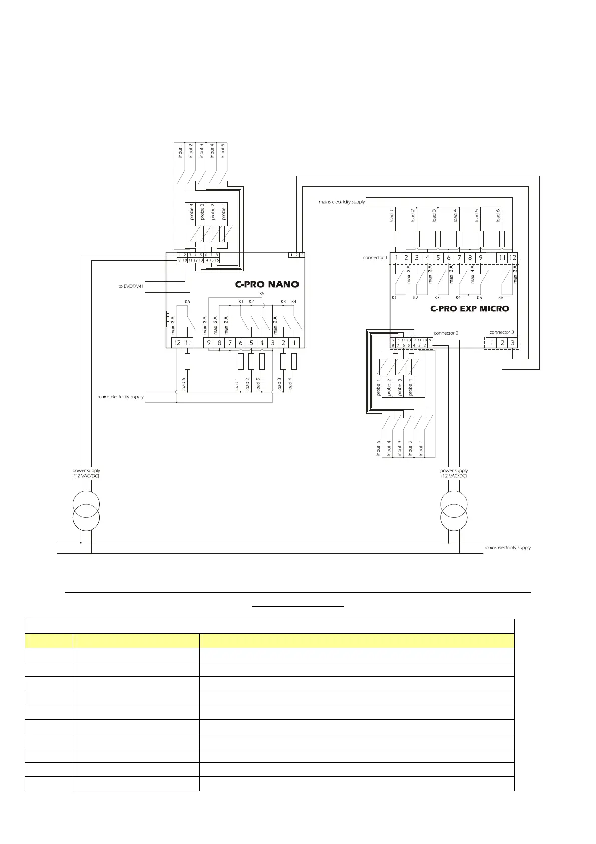
5.1 The C-PRO EXP MICRO wiring layout (IntraBus version)
The references to connecting cable lengths reported in chapter 3 are also valid for I/O expansion units.
The C-PRO EXP MICRO expansion unit wiring layout is shown below, with the meanings of the inputs and
outputs given in the tables.
C-PRO EXP MICRO wiring diagram
The C-PRO NANO and C-PRO EXP MICRO power supplies must be galvanically isolated
from one another.
Connector 1: Output relay connection
Conn. Abbrev. Description
C1-1 DO1 Relay No.1, breaker normally open
C1-2 COMMON DO1 Relay No.1 - common
C1-3 DO2 Relay No.2, breaker normally open
C1-4 COMMON DO2 Relay No.2 – common
C1-5 DO3 Relay No.3, breaker normally open
C1-6 COMMON DO3 Relay No.3 - common
C1-7 DO4 Relay No.4, breaker normally open
C1-8 COMMON DO4, DO5 Relay No.s 4, 5 - common
C1-9 DO5 Relay No.5, breaker normally open
C1-11 DO6 Relay No.6, breaker normally open

 Loading...


