C-PRO NANO HARDWARE MANUAL
Page 8
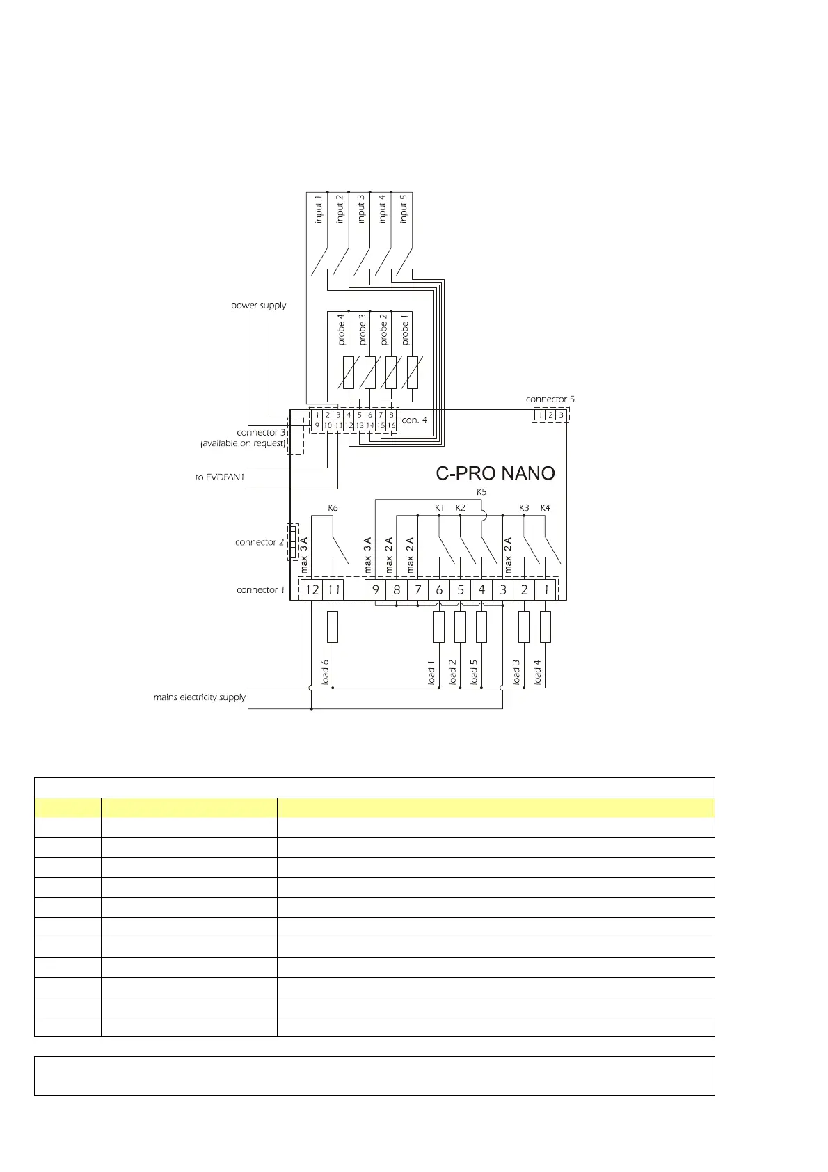
3.2 The C-PRO NANO wiring layout
The C-PRO NANO control unit wiring layout is shown below, with the meanings of the inputs and outputs
given in the tables.
C-PRO NANO wiring diagram
Connector 1: Output relay connection
Conn. Abbrev. Description
C1-1 DO4 Relay No.4, breaker normally open
C1-2 DO3 Relay No.3, breaker normally open
C1-3 COMMON1 Relays No.s 1,2,3,4 - common
C1-4 DO5 Relay No.5, breaker normally open
C1-5 DO2 Relay No.2, breaker normally open
C1-6 DO1 Relay No.1, breaker normally open
C1-7 COMMON1 Relays No.s 1,2,3,4 - common
C1-8 COMMON1 Relays No.s 1,2,3,4 - common
C1-9 COMMON DO5 Relay No.5 - common
C1-10 Not used
C1-11 DO6 Relay No.6, breaker normally open
Connector 2: Connection for the parameter upload/download key and/or output for RS485 module
and/or controller flash download module

 Loading...


