EVCO S.p.A.
EV3 MVC & EVD MVC | Application manual ver. 2.2c | Code 1443DMVCI224
page 30 of 74
5.5.4 Description of connectors for EVJ LCD
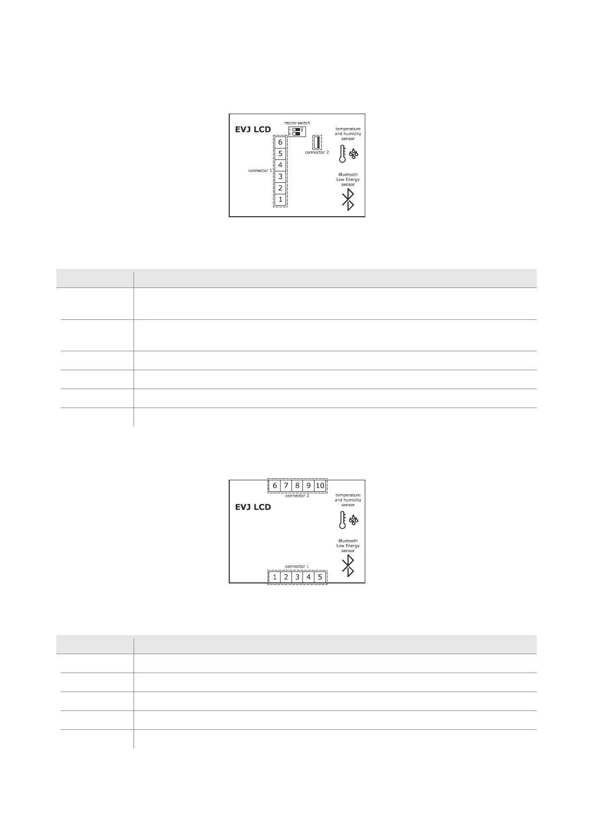
5.5.4.1 Models for wall mounting
The picture below shows the layout of the EVJ LCD connectors.
The table below describes the EVJ LCD connectors. The table gives the maximum provided.
Connector 1
Part Description
1
INTRABUS port reference (GND); signal B (-) in the model with RS-485 port with INTRABUS communication
protocol (purchasing code EVJD900N2VWTX)
2
INTRABUS port signal; signal A (+) in the model with RS-485 port with INTRABUS communication protocol
(purchasing code EVJD900N2VWTX)
3 EVJ LCD (12 VAC/DC) power supply; if EVJ LCD is fed by DC power, connect the negative pole
4 EVJ LCD (12 VAC/DC) power supply; if EVJ LCD is fed by DC power, connect the positive pole
5 unused
6 unused
5.5.4.2 Models for wall mounting with back-slot for in-wall box
The picture below shows the layout of the EVJ LCD connectors.
The table below describes the EVJ LCD connectors. The table gives the maximum provided.
Connector 1
Part Description
1 EVJ LCD (115... 230 VAC) power supply
2 EVJ LCD (115... 230 VAC) power supply
3 unused
4 unused
5 unused

 Loading...