EVCO S.p.A.
EV3 MVC & EVD MVC | Application manual ver. 2.2c | Code 1443DMVCI224
page 28 of 74
5.5.2 Description of connectors for EVD MVC
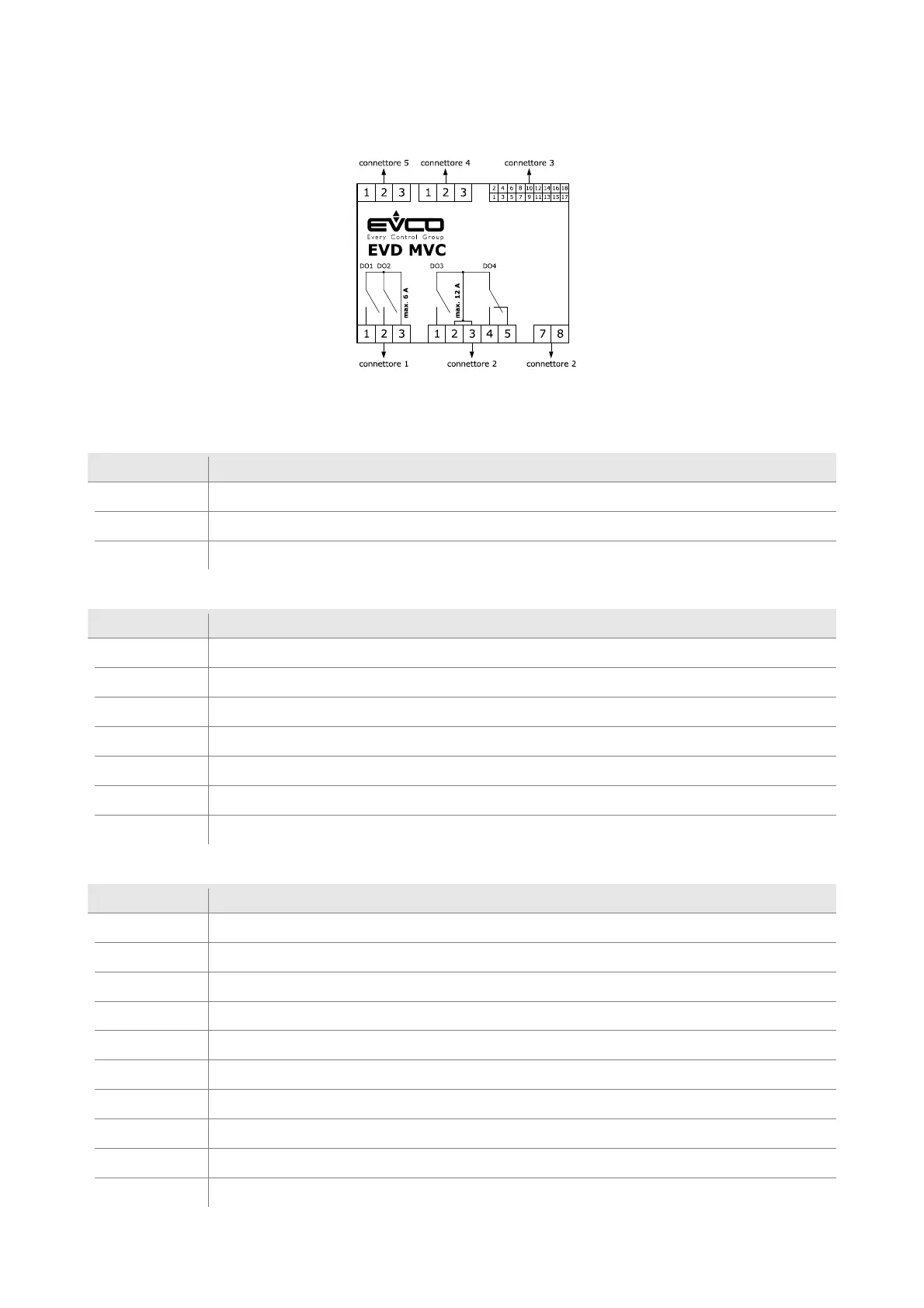
The picture below shows the layout of the EVD MVC connectors.
The tables below describe the EVD MVC connectors.
Connector 1
Part Description
1 relay digital output NO1 (3 A SPST)
2 relay digital output NO 2 (3 A SPST)
3 relay digital outputs CO1/2 (max. 6 A): common
Connector 2
Part Description
1 relay digital output DO3 (12 A SPST): normally open
2 relay digital output DO3 and D04: common
3 relay digital output DO3 and D04: common
4 relay digital output DO4 (8 A SPDT): normally open
5 relay digital output DO4 (8 A SPST): normally closed
7 EVD MVC power supply (115... 230 VAC insulated)
8 EVD MVC power supply (115... 230 VAC insulated)
Connector 3
Part Description
1 Analogue output AO2
2 Analogue output AO1
3 Reference (GND)
4 Dry contact analogue/digital input IN1
5 Dry contact analogue/digital input IN10
6 Dry contact analogue/digital input IN2
7 Dry contact analogue/digital input IN9
8 Dry contact analogue/digital input IN3
9 Dry contact digital input/pulse input IN8
10 Dry contact analogue/digital input IN4

 Loading...