EVCO S.p.A.
EV3 MVC & EVD MVC | Application manual ver. 2.2c | Code 1443DMVCI224
page 7 of 74
2 DESCRIPTION
The following paragraphs contain a description of the various devices that can used for the management of MVC units.
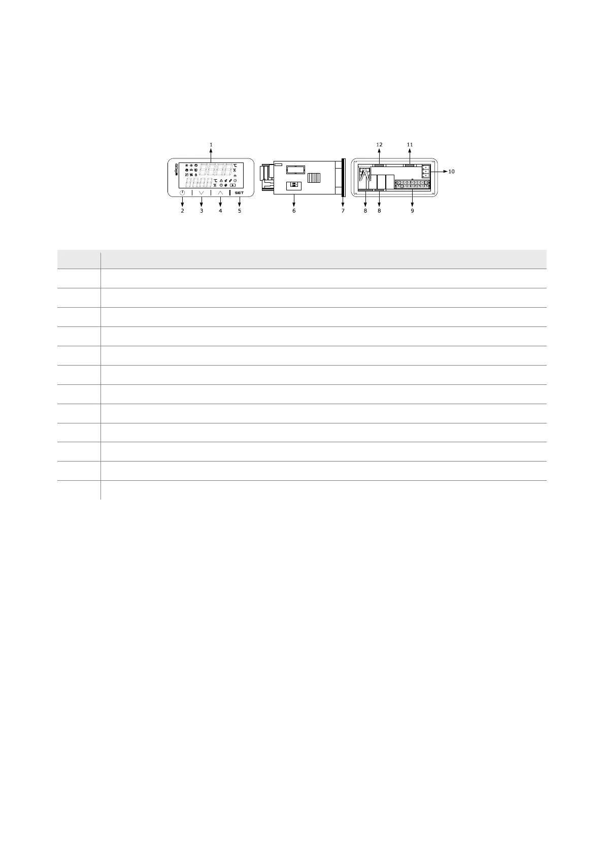
2.1 Description of EV3 MVC
The diagram below shows the layout of the EV3 MVC controller for panel installation in standard 74x32 mm format.
The table below describes each part of the EV3 MVC.
Part Description
1 display
2 on/off key, subsequently also called the on/stand-by key
3 decrease key, subsequently also called the Down key
4 increase key, subsequently also called the Up key
5 setting key, subsequently also called the Set key
6 Micro-switch for the termination resistor for the RS-485 MODBUS line
7 seal
8 edge connector joint for cabling electro-mechanical relay digital outputs (for future reference, digital outputs DO1... DO4
9 male Micro-Fit connector for cabling for power, analogue inputs, digital inputs, analogue outputs and the INTRABUS port
10 plug-in screw terminal block, male only, for cabling for the RS-485 MODBUS port
11 Edge connector joint for the triac output cabling (for future reference, output TK1).
12 Edge connector joint for the triac output cabling (for future reference, output TK2).
The table gives the maximum provided.

 Loading...