EVCO S.p.A.
EV3 MVC & EVD MVC | Application manual ver. 2.2c | Code 1443DMVCI224
page 29 of 74
11 Dry contact digital input/pulse input IN7
12 Dry contact analogue/digital input IN5
13 GND
14 Dry contact digital input IN6
15 unused
16 12 VDC, max. 40 mA
17 Open collector digital output OC1 (12 V, max. 40 mA)
18 Reference (GND)
Connector 4
Part Description
1 Reference (GND)
2 Negative signal RS-485 MODBUS port
3 Positive signal RS-485 MODBUS port
Connector 5
Part Description
1 INTRABUS port reference (GND)
2 INTRABUS port signal
3 12 VDC output
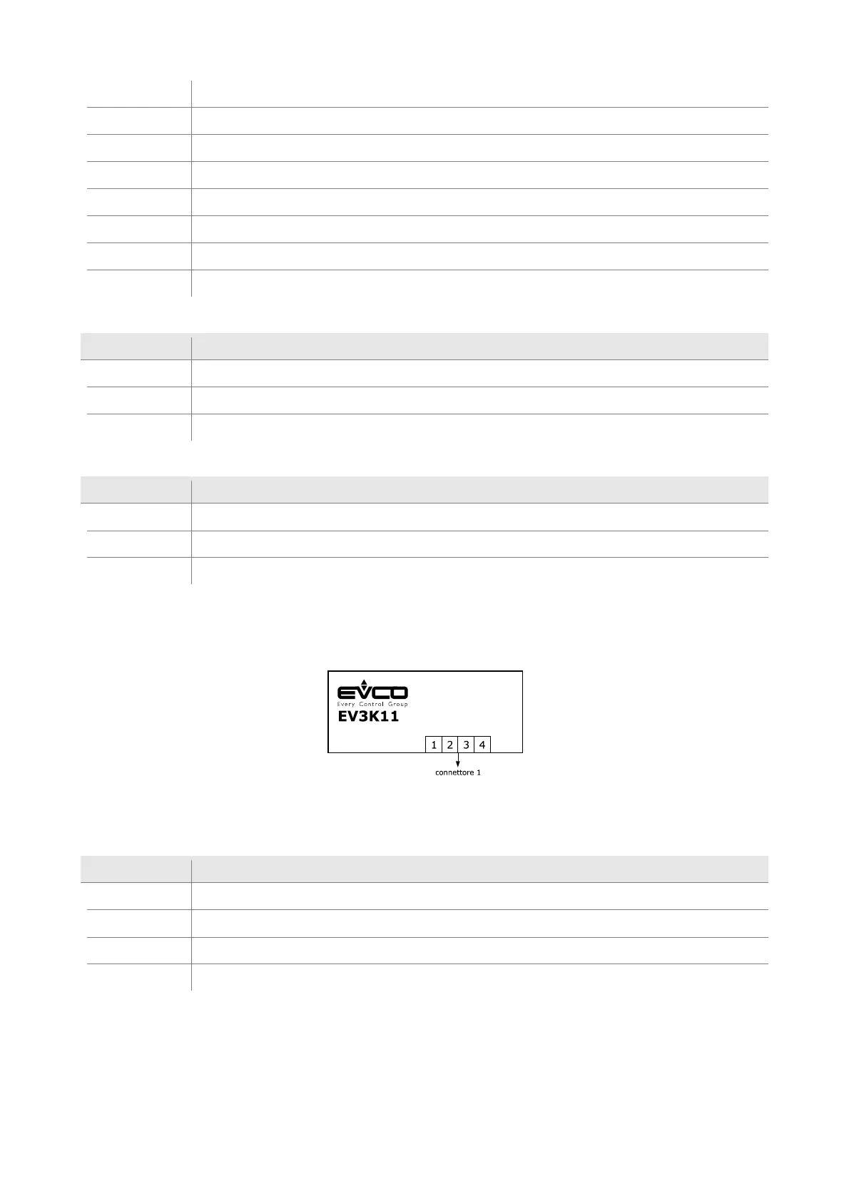
5.5.3 Description of EV3K11 connectors
The picture below shows the layout of the EV3K11 connectors.
The table below describes the EV3K11 connectors.
Connector 1
Part Description
1 EV3K11 (12 VAC/DC) power supply; if EV3K11 is fed by DC power, connect the positive pole
2 power supply EV3K11 and INTRABUS port reference (GND)
3 INTRABUS port signal
4 EV3K11 power supply reference (GND) and INTRABUS port

 Loading...