4
Pre-Installation (continued)
4 IN. P
UMP DESIGN AND OPTIMUM PERFORMANCE
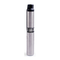
The 4 in. submersible well pumps sold in retail
outlets are designed to pump 10 gallons per minute (10 GPM), which is the average size
home’s use of water per minute. Larger homes will require larger pumps. 4 in. pumps are built with multiple pumping stages, i.e., 6-10
stages, each lifting water to the next stage and to your application. Typically, the deeper the well, the more stages and more motor
horsepower are required to lift the water. The impellers rotating in each stage need to operate in the middle of the stage. Operating above
or below middle may cause the impeller to rub on other stage components, either shortening pump life and/or using excess energy (amp
draw).
PROPER 4 IN. PUMP SELECTIO
N
The proper well depth and
horsepower for 10 GPM 4 in. submersibles are as follows:
HP GPM PUMP DEPTH
IN WELL
1
2
1
-1
ft.
4
1
1
-17
f
.
1
1
17
-2
f
.
NOTE: In irrigati
on applications, i.e. small farms, the stages are designed to pump 20 GPM and the depth of water as follows:
HP GPM PUMP DEPTH
IN WELL
1 2
VOLTAGE
4 in. submersible pumps are offered in 230V. Be sure the volta
ge of the pump you select matches the voltage of the well.
NUMBER OF PUMP WIRES A
ND CONTROL BOXES
4 in. pumps are offered in eit
her 2 wire or 3 wire (the number of wires running from the pump motor).
□ 2-wire motors have 3 wires running from the motor - 2 to provide electric service and 1 ground wire. The motor controls are in the
motor in the well.
□ 2-wire motors are typically used in wells less than 300 ft. in depth and 3-wire motors are used in deeper depths.
□ Some users prefer their motor controls be readily available for service (3-wire and control box mounted near tank), while others
find it unnecessary.
□ 3-wire motors have 4 wires running from the motor - 3 to provide electric service and 1 ground wire. These motors require a motor
control box mounted on the wall near your water tank.
□ 3-wire installations will be more expensive. For example, your wire has more strands in it (4 vs. 3) and they are sold separately.
NOTE: Control box voltag
e and horsepower must match pump voltage and horsepower.
PUMP
CONTROL BOX
HP
OLTAGE HP
OLTAGE
1
2 2
1
2 2
4 2
4 2
1 2
1 2
CONFIRMATION OF SELECTION
Knowing the ab
ove and prior to removing and reinstalling your 4in. pump, please confirm the following:
□ The correct HP for the depth the pump will sit in the well.
□ The correct GPM (gallons per minute) for your well.
□ The correct voltage.
□ The correct number of wires.
□ The correct control box (if applicable).
-1
ft.