HOMEDEPOT.COM
5 Please contact 1-844-883-1872 for further assistance.
Pre-Installation (continued)
PLANNING INSTALLATION
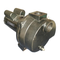
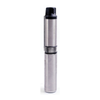
Inspect the
pump and motor for delivery damage. Report any damage immediately to the shipping carrier or to your dealer.
The well driller should thoroughly develop the well (that is, pump out all fine sand and foreign matter) before the pump is installed. See the
Initial Start-Up section of this document.
Pump performance is based on pumping clear, cold, liquid water with no entrained air. Warranty is void in the following conditions:
□ If the pump has pumped excessive sand – excessive sand can cause premature wear to pump.
□ If water is corrosive.
□ If entrained gas or air are present in the water being pumped – these can reduce flow and cause cavitation which can damage pump.
□ If pump has been operated with discharge valve closed – severe internal damage will result.
Install the pump at least 15 to 20 ft. (4.5 to 6 M) below the lowest water level reached with the pump running (lowest draw-down water
level), and at least 5 ft. (1.5M) above the bottom of the well.
GRO
UNDING THE PUMP
WARNING: Risk of el
ectric shock. Can shock, burn or kill. Permanently ground the pump, motor, and control box before connecting the
power supply to the motor.
Ground the pu
mp and motor in accordance with the local codes and ordinances. Use a copper ground wire at least as large as wires
carrying current to motor.
The motor is supplied with a copper ground wire. Splice this ground wire to a copper conductor that matches motor wire size specified in
Wiring Connections for wire splicing instructions.
Permanently ground the pump, motor and control box before connecting the power cable to power supply. Connect the ground wire to the
approved ground first and then connect to the equipment being installed.
Do not ground to a gas supply line.
WARNING: Risk of el
ectric shock and fire. Can shock, burn or kill. If using a drop wire larger than No. 10 (5.5 mm
2
) (for exampl
e, No. 8
(8.4mm
2
) wire) between the pum
p and control box, run wire to a separate junction box. Connect the junction box to the control box with a
No. 10 (5.5 mm
2
) or smal
ler wire (depending on amp rating of the pump). For more information, contact your local code officials.
Wiring Connections
All wiring must
meet National Electrical Code or Canadian Electrical Code and local code requirements. Use only copper wire when making
connections to pump and control box.
To avoid over-heating wires and excessive voltage drop at the motor, ensure the wire size is at least as large as the size listed in the
following tables for your horsepower pump and length of wire run.
NOTICE: When built-in overheating protection is not provided, use with an approved overload equipped motor control that matches motor input in full
load amps. Select or adjust overload element(s) in accordance with control instructions. When built-in overheating protection is provided, use with an
approv
ed motor control that matches motor input in full load amperes.
Recom
mended Fusing Data - 60 Hz., Single Phase, 3 Wire
Submer
sible Pump Motors
Recom
mended Fusing Data - 60 Hz., Single Phase 2 Wire
Submer
sible Pump Motors
HP
olt
s Fuse Size
n
D
l
.B.
1
2 2
1
1
1
4 2
2
1
2
1 2
1
2
HP
olt
s
Fuse S
ize
n
D
l
.B.
1
22
1
1
1
42
1
1
1