7700FR/7800FR MultiFrame
7800TR-32x24 Modular Tally Router
Revision 1.2 Page - 13
3.5 GENERAL PURPOSE INPUTS
There are 24 General Purpose Inputs (GPIs) available on the two 62-pin D-Sub connectors on the rear
plate. The GPIs are “wet” meaning they need external voltage to function. The GPI ports are used to
read the tallies (GPOs) from products such as a vision mixer (production switcher). The pinout of these
connectors is shown in Figure 3-4.
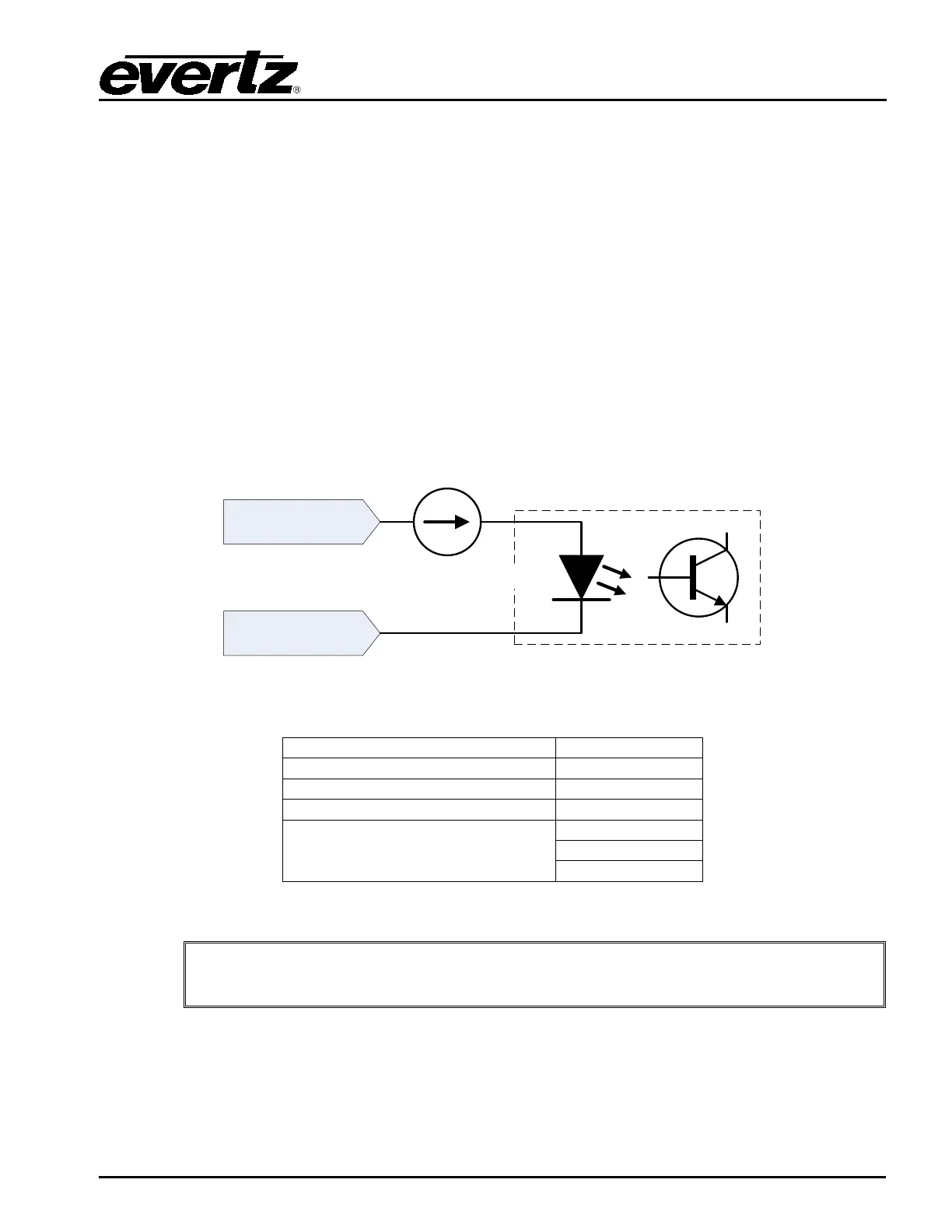
Note that the GPI inputs are polarity sensitive. The circuit diagram is shown in Figure 3-5 and the
electrical specifications are in Table 3-5 and also in Section 2.1. The GPI input is protected by a
current source which limits the current into an optoisolator. The optoisolator is used to protect the tally
router’s internal circuitry, and also to isolate the GPIs from each other. If more than +/- 24 volts is
applied to a GPI it may become damaged but the damage will be isolated to the particular GPI.
The selected Wet Power source is available on three pins of each D-Sub connector as WET+ and
GND. This wet power can be used to wire the GPIs as “Dry”. Please see Section 3.8 for more
information on the wiring and the Wet/Dry terminology.
GPI +
GPI -
~10 mA
~1.4 V
optoisolator
Figure 3-5: Rear GPI Input Schematic
Maximum Reverse GPI Voltage
GPI Current Limiting
Table 3-5: Rear GPI Input Electrical Specifications
Do not apply a voltage higher or lower than the maximums or the
permanently damaged.