EasyManua.ls Logo

evertz 7800TR - 7800 TR-BHP General Purpose Output Connections; Figure 3-7: Optional 7800 TR-BHP Bulkhead Panel; Figure 3-8: 7800 TR-BHP GPO in Wet Mode Circuit Diagram

evertz 7800TR
36 pages
Print Icon
To Next Page IconTo Next Page
To Previous Page IconTo Previous Page
Loading...
7700FR/7800FR MultiFrame
7800TR-32x24 Modular Tally Router
Page - 18
Revision 1.2
WET
DRY
1
WET
DRY
2
WET
DRY
3
WET
DRY
4
WET
DRY
5
WET
DRY
6
WET
DRY
8
WET
DRY
9
WET
DRY
10
WET
DRY
11
WET
DRY
12
WET
DRY
13
WET
DRY
14
WET
DRY
32
WET
DRY
15
WET
DRY
32
WET
DRY
16
WET
DRY
17
WET
DRY
18
WET
DRY
19
WET
DRY
20
WET
DRY
21
WET
DRY
22
WET
DRY
23
WET
DRY
24
WET
DRY
25
WET
DRY
26
WET
DRY
27
WET
DRY
28
WET
DRY
29
WET
DRY
32
WET
DRY
30
WET
DRY
31
WET
DRY
32
WET
DRY
7
DRY WET
1
DRY WET
2
DRY WET
3
DRY WET
4
DRY WET
5
DRY WET
6
DRY WET
7
DRY WET
8
DRY WET
9
DRY WET
10
DRY WET
11
DRY WET
12
DRY WET
13
DRY WET
14
DRY WET
15
DRY WET
16
DRY WET
17
DRY WET
18
DRY WET
19
DRY WET
20
DRY WET
21
DRY WET
22
DRY WET
23
DRY WET
24
TR
4800-BHP
WET PWR
SN
Figure 3-7: Optional 7800TR-BHP Bulkhead Panel
When connecting the rear D-Sub cables, be careful to connect the correct cable
to the ports on the rear of the 7800TR-BHP.
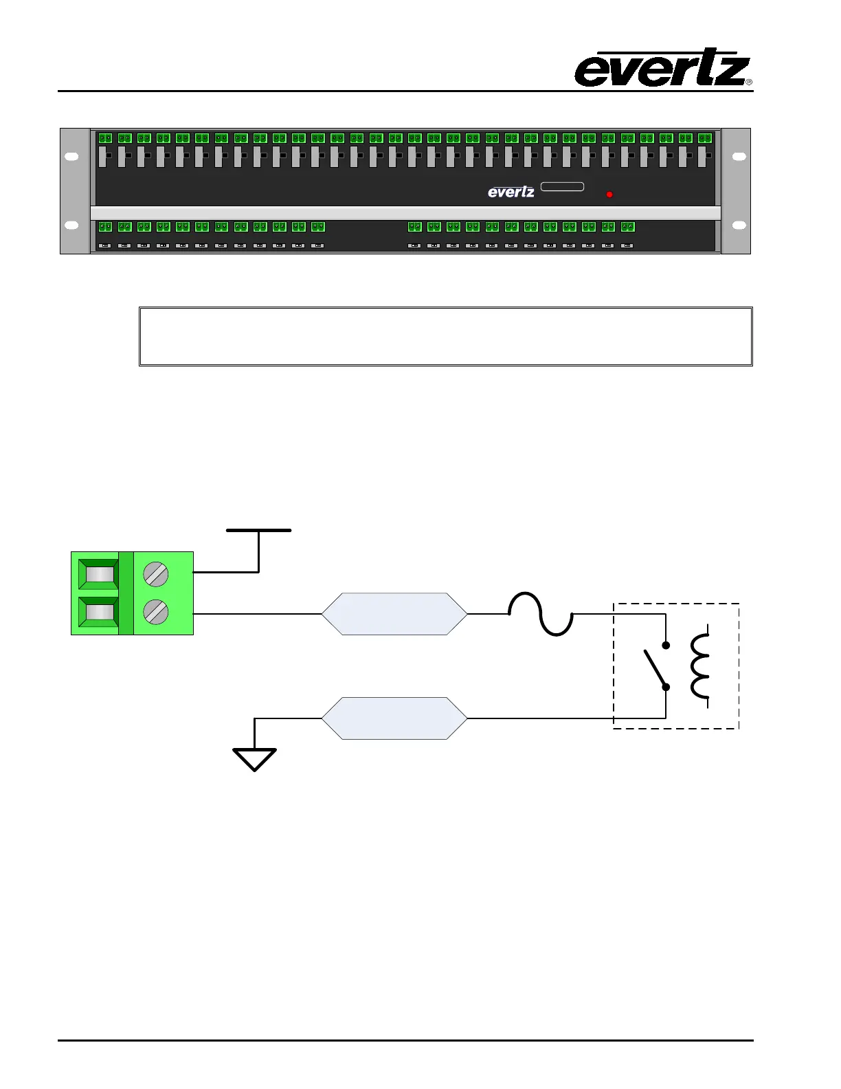
3.9.1 7800TR-BHP General Purpose Output Connections
The rear 32 General Purpose Outputs from the tally router are broken out to 48 terminal blocks across
the top of the bulkhead panel. Each GPO has a slide switch below it to select between Wet and Dry
modes (see section 3.8.1). The circuit diagrams for the GPOs in both modes are shown in Figure 3-8
and Figure 3-9.
GPO B
0.
15A max
WET GPO
1
2
+WET
GPO A
WET
-
Figure 3-8: 7800TR-BHP GPO in Wet Mode Circuit Diagram

Table of Contents

Related product manuals