XT Series DISK RECORDER - Technical Reference
EVS Broadcast Equipment SA - Nov 2005
Issue 3.0
39
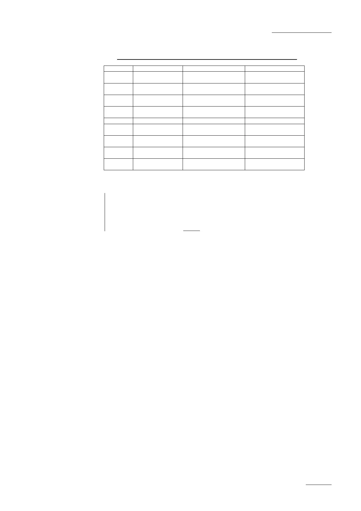
4.2.5.4 CONNECTORS ON THE COD A AND COD B MODULES
Connector SD mode HD mode Connector label on rear panel
J1 SDI/CVBS (*)
monitoring output (SD)
SDI/CVBS(*) monitoring output
(SD, down-converted)
Character Outs, CVBS/SDI
J2 SDI monitoring output
(SD)
SDI monitoring output
(SD, down-converted)
Not connected
J3 Loop-through for the
SDI input signal (SD)
SDI program output
(SD, down-converted)
SD Out
J4 SDI monitoring output
(SD)
HD SDI monitoring output
(HD)
Character Outs, SD/HD
J5 Not installed Not installed n.a.
J6 SDI program output
(SD)
HD SDI program output
(HD)
SD/HD Out
J7 SDI program output
(SD, identical to J6)
HD SDI program output
(HD, identical to J6)
SD/HD Out
J8 SDI input
(SD)
HD SDI input
(HD)
SD/HD In
J9 Alternate SDI input
(SD, for hardware loop)
Alternate HD SDI input
(HD, for hardware loop)
Not connected
(*) the switch between SDI and CVBS on J1 is done by a software setting in the EVS Configuration Menu
Note : Only front backplanes labelled BKP7 are compatible with COHX boards (4 slots for 4U
frames, and 7 slots for 6U frames). The BKP7 backplanes (compatible with COHX
boards) have 3 rows of soldering per slot, while the backplanes compatible with IO-E,
COHD or COHU boards have 2 rows of soldering per slot. Note that the top slot of
BKP7 backplanes must always be connected to the HCT-X board.
 Loading...


![Preview: EVS XT[2]](https://data.easymanua.ls/products/617905/200x200/evs-xt-2.webp)


