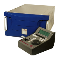
XT Series DISK RECORDER - Technical Reference
EVS Broadcast Equipment SA - Nov 2005
Issue 3.0
42
4.4.1.1 7-SEGMENT DISPLAY:
This display notices the stages and errors of the system boot processing.
Left Right
0 0 4.4.1.1.1.1 OK
0 1 Communication RAM error
0 2 SDRAM Error
0 3 4.4.1.1.1.2 Restarted by watchdog
If an error 01, 02 or 03 occurs, the nearby LED lights RED
Note:
The MODE buttons modify internal EVS parameters. Do not modify.
4.4.1.2 LED’S INFORMATION:
While the program is loading, LED’s A, B, C and D give the following
information about RAM SIMM’s testing process:
A B C D
- - - -
4.4.1.2.1.1 At
start-up
- - - ON
Testing communication RAM
- - ON -
Clearing communication RAM
- - ON ON
4.4.1.2.1.2 Polling
basic user commands
- ON - -
Testing the first 256KB SDRAM
- ON - ON
256KB SDRAM is OK
ON ON ON -
Communication RAM error
ON ON - ON
SDRAM error
4.4.1.3 SDTI CONNECTORS:
IN: SDTI input
OUT/LP: SDTI output
When the LSM-XT is connected to the SDTI network, if L1 LED is ON, the
system is in HARDWARE MASTER mode (“SERVER” in EVS Configuration
Menu), and if L1 LED is OFF, the system is in HARDWARE SLAVE mode
(“CLIENT” or “MASTER” in EVS Configuration Menu). The other two LEDs
are not in use at the moment. 1 (and only 1
) XT on the SDTI network must
operate in Hardware Master mode. Refer to the SDTI Network section for
details.

 Loading...