Machine description – quick overview
Inside view
099-005401-EW501
17.06.2014
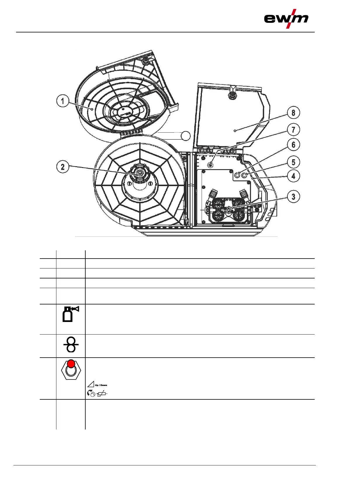
4.3 Inside view
Figure 4-3
Wire spool protective cap
Lighting, inside
In power-saving mode and with MMA or TIG welding, the lighting is switched off.
Gas test push-button
The welding voltage and wire feed motor remain off while testing and setting the gas
flow volume. This provides a high degree of safety for the welder, since the arc cannot
be inadvertently ignited. Shielding gas flows only as long as the button is held.
Push-button, wire inching
For inching the wire electrode after changing wire spools. (The welding wire is inched
through the hose package to the welding torch without any voltage or gas).
Changeover switch for machine operation (operating point)
The operating point (wire speed/welding voltage) can be set at the wire feed unit
control, with a remote control or using an up/down welding torch.
Set operating point with up/down welding torch.
Set operating point at the wire feed unit control or remote control (standard).
Protective cap
Cover for the wire feed mechanism and other operating elements.
Depending on the machine series, you can find additional stickers with information on
the operation and maintenance of the machine on the inside of the cap.