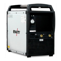
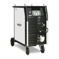
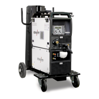
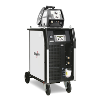
Design and function
Interfaces
099-005320-EW501
22.05.2014
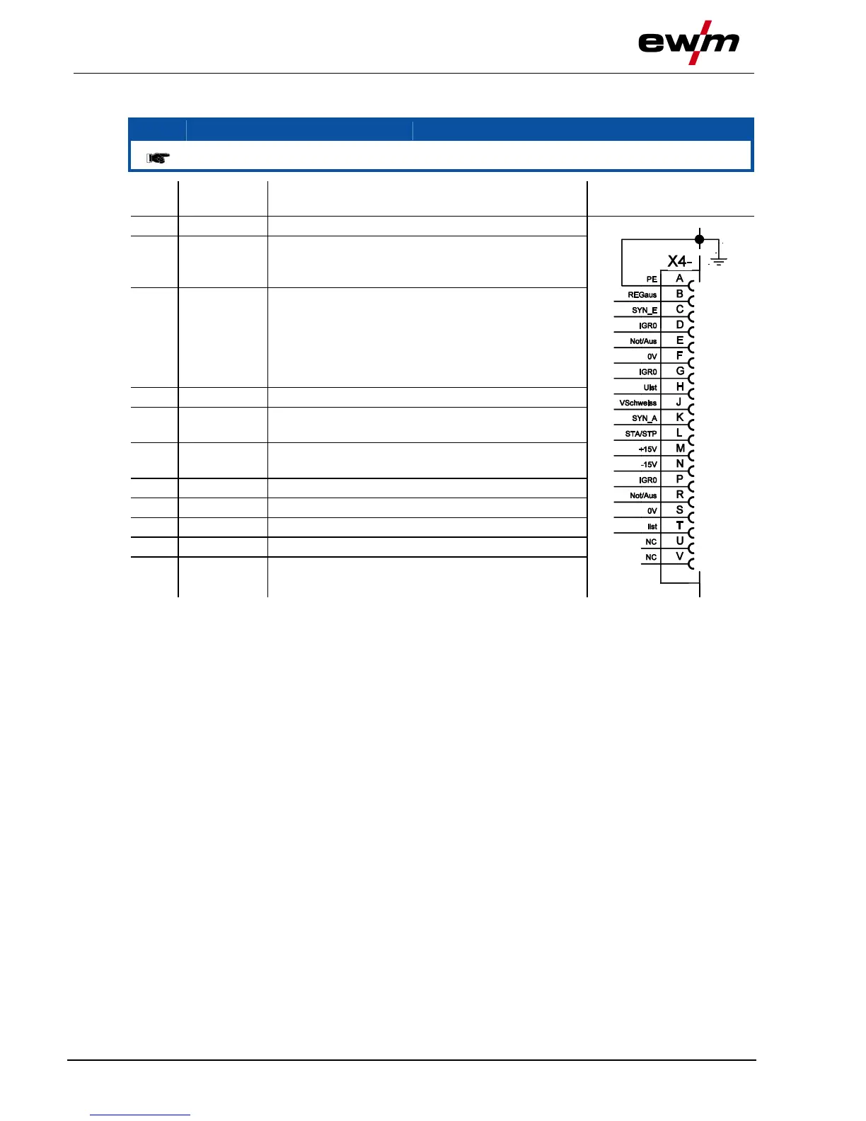
5.16.1 Automation interface
These accessory components can be retrofitted as an option, see Accessories chapter.
PE Connection for cable shielding
IGRO Current flows signal I>0 (maximum load 20
mA / 15 V)
0 V = welding current flows
Not/Aus Emergency stop for higher level shut-down
of the power source.
To use this function, jumper 1 must be
unplugged on PCB M320/1 in the welding
machine. Contact open welding current
off
I>0 Power relay contact, galvanically isolated
(max. +/-15 V / 100 mA)
Uist Welding voltage, measured against pin F,
0-10 V (0 V = 0 V; 10 V = 100 V)
Str/Stp Start = 15 V / Stop = 0 V
1)
+15 V Voltage supply (max. 75 mA)
-15 V Voltage supply (max. 25 mA)
Iist Welding current, measured on pin F;
0-10 V (0 V = 0 A, 10 V = 1000 A)
1
) The operating mode is given by the wire feed unit (the start / stop function equates to pressing
the torch trigger and is used in mechanised applications, for example).