Maintenance
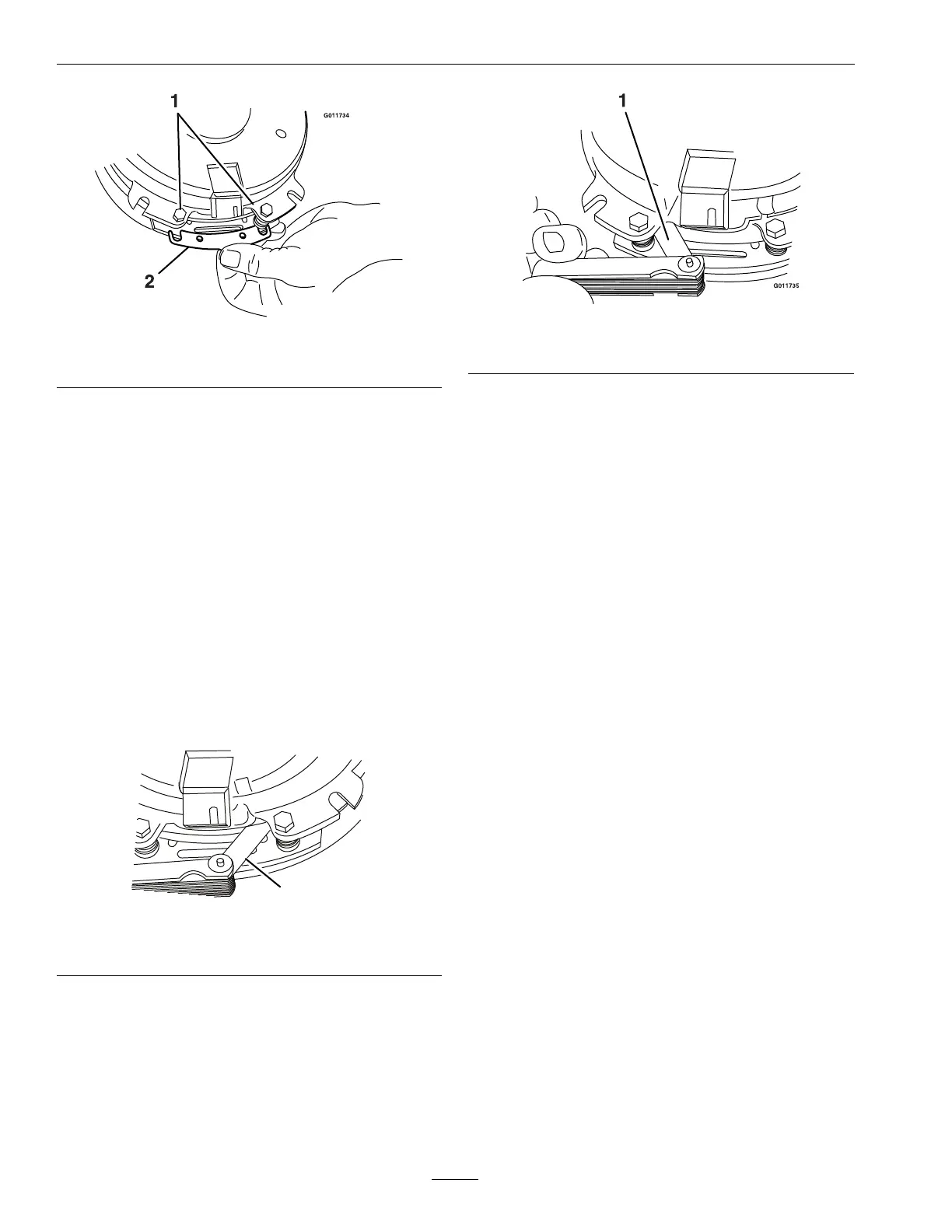
Figure28
1.Brakemountingbolt
2.Shim
B.Usingneedlenosepliers,orbyhand,take
holdofthetabandremovetheshim(DoNot
discardtheshimuntilproperclutchfunction
hasbeenconrmed).
C.Usingapneumaticline,blowoutanydebris
fromunderthebrakepoleandaroundthe
brakespacers.
D.Re-torqueeachbolt(M6x1)to10ft-lb(13
N-m)+/-0.5ft-lb(0.7N-m).
E.Usinga0.010inchthickfeelergauge,verify
thatagapispresentbetweentherotorand
armaturefaceonbothsidesofthebrakepole
asshown.(Duetothewaytherotorand
armaturefaceswear(peaksandvalleys)itis
sometimesdifculttomeasurethetruegap.)
Figure29
1.Feelergauge
Figure30
1.Feelergauge
•Ifthegapislessthan0.010inch,then
reinstalltheshimandreferencethe
Troubleshootingsection.
•Ifthegapissufcient,proceedtothe
safetycheckinstepF.
F.Performthefollowingsafetycheck:
a.Sitontheseatandstarttheengine.
b.MakesurethebladesDoNotengagewith
thePTOswitch“off”andtheclutch
disengaged.
Iftheclutchdoesnotdisengage,
reinstalltheshimandreferencethe
Troubleshootingsection.
c.EngageanddisengagethePTOswitch
tenconsecutivetimestoensuretheclutch
isfunctioningproperly.Iftheclutch
doesnotengageproperly,referencethe
Troubleshootingsection.
ForwardSpeedAdjustment
1.Parkthemachineonalevelsurface.
2.Shutoffengineandwaitforallmovingpartsto
stop.Engageparkingbrake.
3.Releaseandlowertherearcushionfromtherear
ofthemachine.
4.Placethefrontreference/speedcontrolbarin
themaximumforwardposition.SeeAdjusting
theFrontReference/SpeedControlBarin
Operation.
5.PushtheRHcontrolleverallthewayforwardto
thefrontreference/speedcontrolbar.
6.LoosenthejamnutsontheturnbuckleontheRH
motioncontrol(asviewedfromtherearofthe
38
 Loading...