Maintenance
Adjustments
Note:DisengagePTO,shutoffengine,waitfor
allmovingpartstostop,engageparkingbrake,and
removekeybeforeservicing,cleaning,ormakingany
adjustmentstotheunit.
CAUTION
Raisingthemowerforserviceormaintenance
relyingsolelyonmechanicalorhydraulic
jackscouldbedangerous.Themechanicalor
hydraulicjacksmaynotbeenoughsupportor
maymalfunctionallowingtheunittofall,which
couldcauseinjury.
DoNotrelysolelyonmechanicalorhydraulic
jacksforsupport.Useadequatejackstandsor
equivalentsupport.
DeckLeveling
Note:Smalladjustmentscanbeaccomplishedby
increasingthetirepressureinthetireonthelowside.
1.Parkthemachineonalevelsurfaceanddisengage
thebladecontrolswitch.
2.Stopengine,waitforallmovingpartstostop,and
removekey.Engageparkingbrake.
3.Checktheairpressureinthedrivetires.Ifneeded,
adjusttotherecommendedination;referto
CheckingtheTirePressureinDriveSystem
Maintenancesection.
4.Settheheightofcutlevertothe3inch(7.6cm)
position.
5.Raisethedischargedeector.
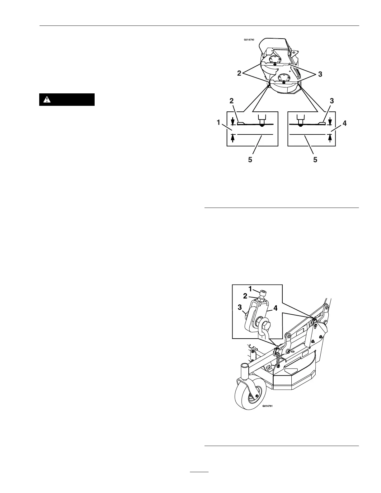
6.Carefullyrotatethebladesfronttorear.Measure
fromthetipofthefrontbladetothelevelsurface
(Figure22).Thebladesshouldmeasure3inches
(7.6cm).
Note:Inmostconditions,thebacktipsshould
beadjusted1/4inch(6.4mm)higherthanthe
front.
Figure22
1.31/4inches(8.3cm)4.3inches(7.6cm)
2.Backbladetip
5.Levelsurface
3.Frontbladetip
7.Usethenetuneadjustmentsonthefrontdeck
liftarmstoadjusttheheightofthefrontblade
tips.Loosenthewhizlocknutonthesideof
theyokeandthejamnutontop.Finetune
thescrewadjusterbyturningittoget3inches
(7.6mm)height.Toincreasetheheight,turn
theadjusterscrewclockwise;todecrease,turn
counterclockwise(seeFigureFigure23).
Figure23
1.Adjusterscrew3.Whizlocknut
2.Jamnut4.Yoke
35




 To Next Page