Maintenance
CuttingHeightAdjustmentTable(1inchto41/4inches(2.5cm-10.8cm))(cont'd.)
NumberOfSpacers
BelowCaster
SupportHubNumberof1/4inch(.64cm)BladeSpacersBelowSpindle
Cutting
Height
Range
Axle
Position
(Figure9)
1/2
inch
(1.2cm)
3/16
inch
(.48cm)43210
31/8–
41/8inches
(7.9–10.5
cm)E40
31/8inch
(7.9cm)
33/8inch
(8.6cm)
35/8inch
(9.2cm)
37/8inch
(9.8cm)
41/8inch
(10.5cm)
31/4–
41/4inches
(8.3–10.8
cm)E41
31/4inch
(8.3cm)
31/2inch
(8.9cm)
33/4inch
(9.5cm)
4inch
(10.1cm)
41/4inch
(10.8cm)
Important:AlwaysadjusttheNumberofSpacersbelowCasterHubtocorrespondtotheAxle
Positionasshownintabletoobtainproper“rake”(bladesshouldalwaysbeleveltotheground
ortippedslightlydownatthefront).
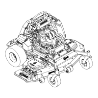
AdjustingtheAxlePosition
Desiredcuttingheightrangecanbeobtainedby
adjustingtherearaxleandplacingcasterspacers
aboveorbelowthecasterarm(seeFigure9and
Figure10alongwiththeCuttingHeightAdjustment
Chart).
Toadjustrearaxle:
1.Stopthemachineandmovethedriveleversto
theneutrallockposition.
2.DisengagethePTO.
3.Raisetherearofthemachineupontojackstands
andremovethedrivewheels.
4.Loosenbutdonotremovethetoptwobolts
oneachhydraulicmotormountingbracket(see
Figure9).
5.Removethebottomsetsofhardwareforeach
bracket.
6.Repositionthemountingbrackettothedesired
heightandreinstallthebottomhardware.
7.Tightenallhardwareandremountdrivewheels.
8.Removejack.
9.Adjustwheeldriveandbrakelinkagesas
required(seeBrakeandWheelDriveLinkage
Adjustmentsection).
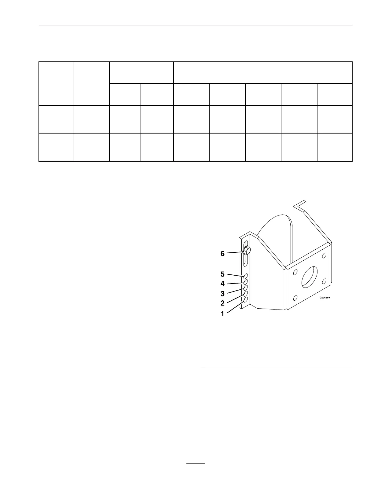
g006959
Figure9
1.PositionA4.PositionD
2.PositionB5.PositionE
3.PositionC
6.AxlePivotBolt-loosen
butDoNotremove
Note:Theaxlepositionsarein1/2inch(1.3cm)
incrementsandthelargecasterspacersare1/2
inch(1.3cm)thick.Therefore,byadjustingthe
samenumberof1/2inch(1.3cm)casterspacersas
axleholepositionsthebladeswillretainthesame
front-to-backtip(rake).
33