Maintenance
AdjustingtheNumber
ofSpacersbelowCaster
SupportHub
1.Stopthemachineandmovethedriveleversto
theneutrallockposition.
2.DisengagethePTO.
3.Placethedriveleversinthe“parkbrake”position.
4.Pushdownonhandlestoliftfrontcastersoffthe
ground.
5.Supportwithjackstands.
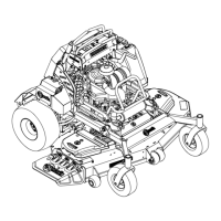
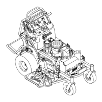
6.Remove“quickpin”fromonecasterandremove
casterfromhub(seeFigure10).
g006797
Figure10
1.Four1/2inch(127mm)
spacers
3.3/16inch(4.8mm)
spacer
2.QuickPin4.Castersupport
7.Adjustthenumberof1/2inchspacersbetween
bottomofhubandcasteryoketoobtainthe
desiredcuttingheightfromtheCuttingHeight
AdjustmentTableintheAdjustingtheCutting
Heightsection.
8.Installremainingspacersontopofhub.
9.Install“quickpin”.
10.Repeatforothercaster.
AdjustingtheCuttingHeight
withBladeSpacers
1.Stopthemachineandmovethedriveleverstothe
neutrallockedposition.
2.DisengagethePTO.
3.Engagetheparkbrake.
4.Stoptheengine,removethekeyandwaitforall
movingpartstostop.
5.Bladesmaybeadjustedforcuttingheightbyusing
thefour1/4inch(.64cm)spacersfoundonthe
bladespindlebolts(factorysettingistwoabove
andtwobelow).Thisallowsa1inch(2.5cm)
rangein1/4inch(.64cm)incrementsofcutting
heightinanyaxleposition.Thesamenumber
ofbladespacersmustbeusedonallbladesto
achievealevelcut(twoaboveandtwobelow ,one
aboveandthreebelow,etc.).
6.Raisefrontofdeckandsupportwithjackstands.
7.Holdbladeboltonbottomandloosenspindle
nutontop.
8.Adjustnumberofspacersbetweenbottomof
spindleandbladeasindicatedintheCutting
HeightAdjustmentTableandnotesinthe
AdjustingtheCuttingHeightsection.
9.Installunusedspacersbetweentopofspindleand
spindlenut.
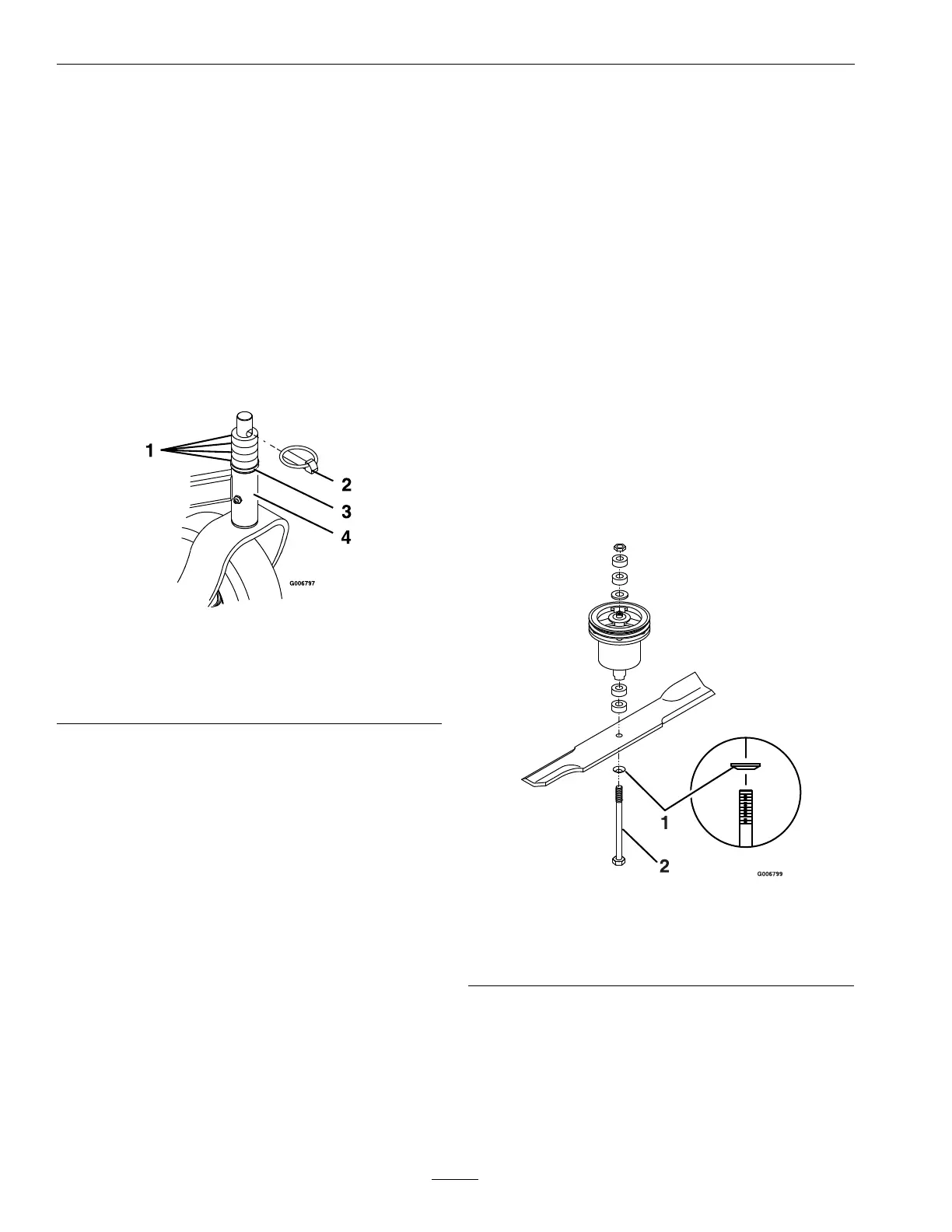
10.Torqueboltto75–80ft-lb(102–109N-m)(see
Figure11).
g006799
Figure11
1.Springdiscwasher
(conetowardsbolthead)
2.Bladebolttorqueto
75–80ft-lb(102–109
N-m)
PTOEngagementLinkage
Adjustment
LocatedbetweenthePTOengagementbellcrankand
PTOengagementassistarmbeneaththefront,left
handcorneroftheenginedeck.
34