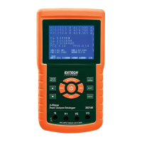
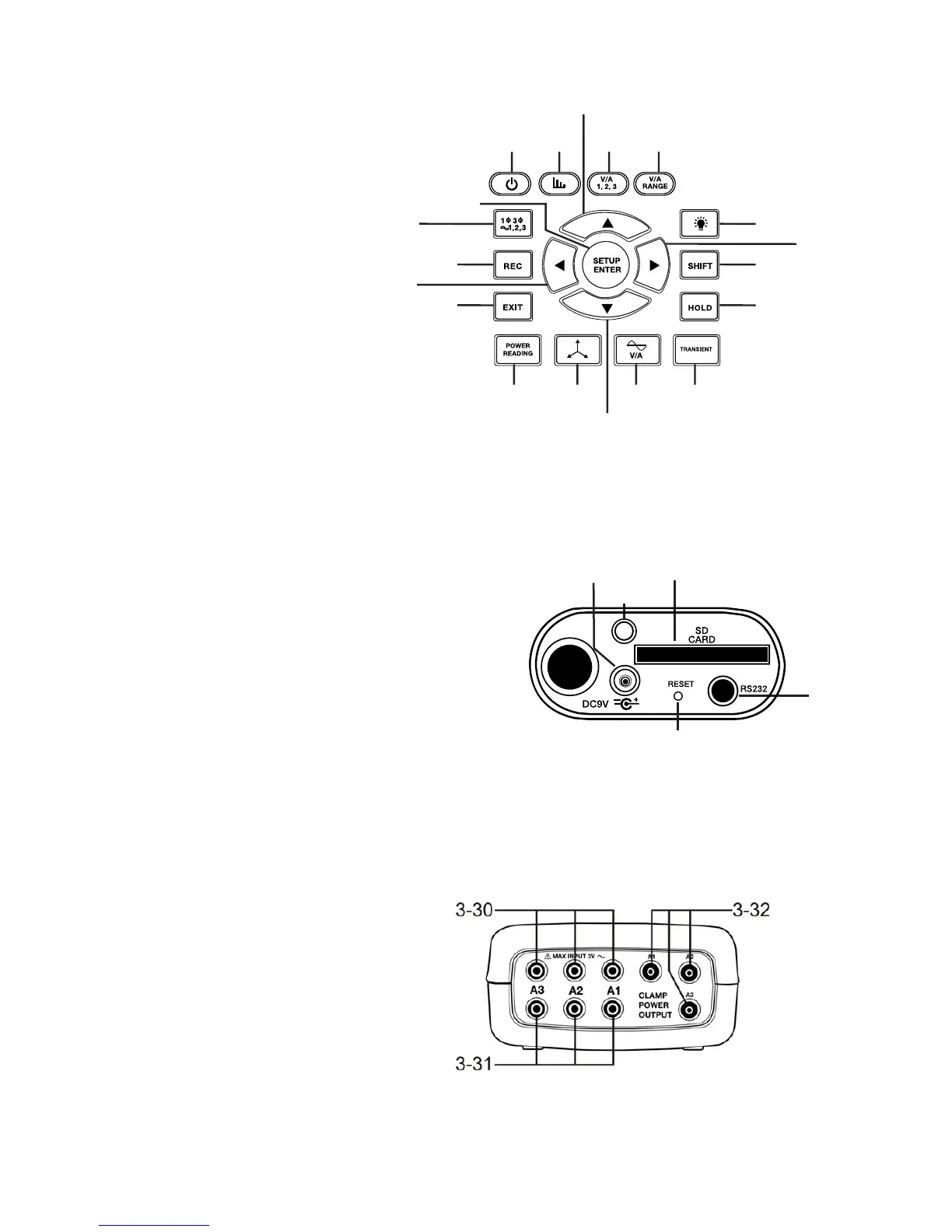
Keypad Description
3-6
Display Backlight ON-OFF
3-7
Power ON-OFF
3-8
Exit (programming)
3-9
REC datalogger memory
3-10
Volt/Amp range
3-11
Shift (programming)
3-12
Setup / Enter
3-13
HOLD (freeze display)
3-14
Transient display
3-15
V/A Waveform display
3-16
Phasor display
3-17
Power Measurement
3-18
▲
up arrow navigation
3-19
▼down arrow
navigation
3-20
◄
left arrow navigation
3-21
►
right arrow navigation
3-22
Phase / Wire setup
3-23
Harmonics display
3-24
Harmonics Analysis display
3-25
3-26
3-28
3-27
3-29
Meter Right Side
3-25
9V power adaptor jack
3-26
SD memory card socket
3-27
RS232 PC interface socket
3-28
Reset button
3-29
Screw fastener for protective cap
Meter Top
3-30
Clamp positive input jacks
3-31
Clamp negative input jacks
3-32
Clamp power lead connections
Note: The Battery compartment and Tilt Stand are located on the rear of the instrument
3-6
3-7
3-8
3-9
3-10
3-11
3-12
3-13
3-18
3-19
3-20
3-21
3-16 3-15 3-143-17
3-22
3-23 3-24