CHAPTER 27
PAGE 7
MAINTENANCE MANUAL EXTRA 300/SC
PAGE DATE: 1. August 2014
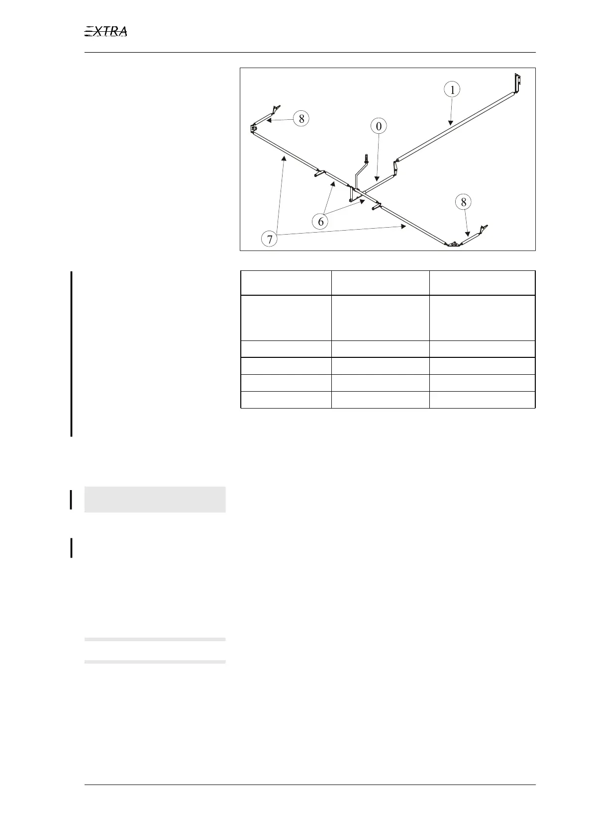
Figure 6 Control Rod Identification
Control Rod Measurement Rod end alignment
0 821 mm
Fixed rod end.
Do not adjust!
0°
1 2235 mm 0°
6 520 mm 90°
7 1231 mm 0°
8 405 mm 90°
Table 1 Control Rod Measurement & Rod End Alignment
Length Adjustment
I M P O R T A N T Do not adjust control rod No 0 (See Figure 6). This con-
trol rod has a fixed length.
The standard measurements are given in Table 1.
1 Remove the respective access panels.
2 Disconnect one rod end from the respective bellcrank.
3 Loosen the check nut.
N O T E It might be necessary to adjust both rod ends to get the
correct length. In this case the free thread of both rod
ends should have the same length.