CHAPTER 27
PAGE 8
MAINTENANCE MANUAL EXTRA 300/SC
PAGE DATE: 1. August 2014
I M P O R T A N T Ensure that the rod ends of each control rod are ex-
actly aligned to each other (see Table 1) after adjust-
ment. This particularly applies for the control rod (1,
Figure 6), which must allow the torque tube to rotate.
I M P O R T A N T Observe that the rod ends joined to the rocker type
bellcrank should be adjusted long enough not to obstruct
the travel.
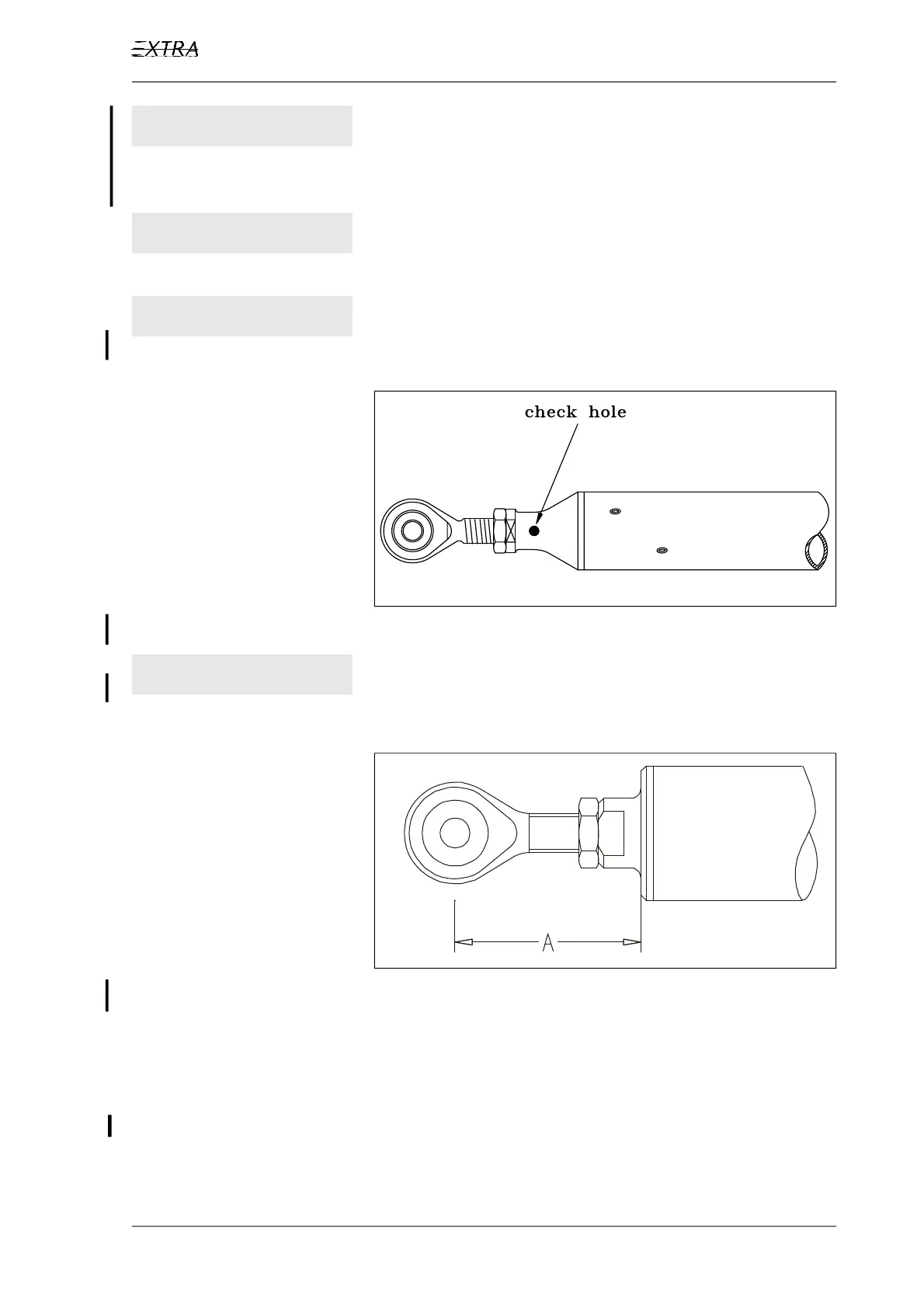
I M P O R T A N T Ensure that the threaded rod is visible in the check hole
(Figure 7, Sheet 1) in any case, if aluminium rods shall
be adjusted.
Figure 7, Sheet 1 Aluminium Control Rod Check Hole
I M P O R T A N T Ensure that the value "A" (Figure 7, Sheet 2) does not
exceed 43 mm in any case, if carbon rods shall be ad-
justed.
Figure 7, Sheet 2 Carbon Control Rod Maximum Adjustment
4 Turn the rod end in the desired direction to change the length.
5 Ensure that the rod end is in proper alignment with the re-
spective control lever and tighten the check nut.
6 Reinstall the control rod per Chapter 27-00-01.
7 Ensure that the control rods don't jam when the control sticks
are moved between the extreme positions.