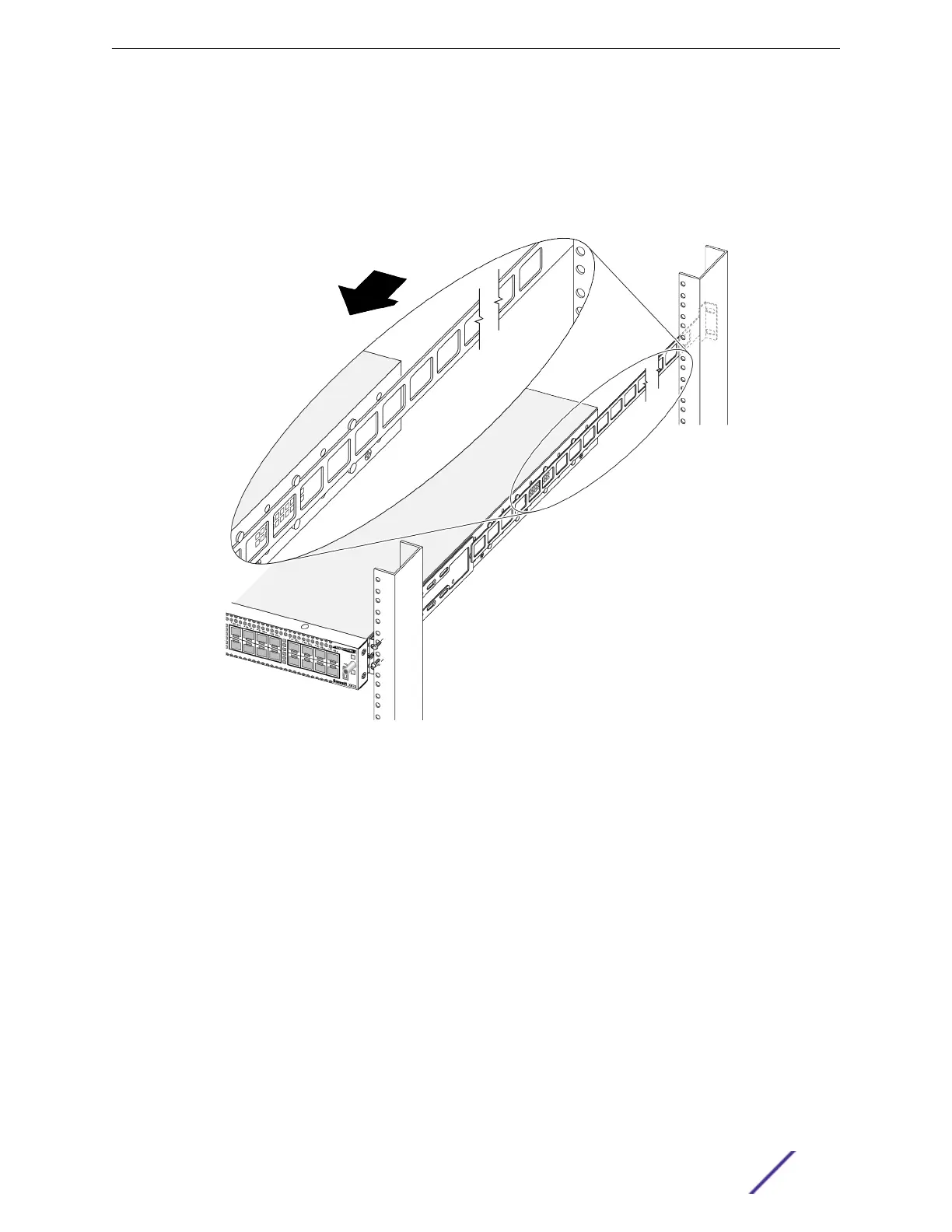
6 If you are mounting the switch in a four-post rack or a cabinet, secure the rear mounting brackets
(rails).
Otherwise, skip to step 7 on page 39.
a At the rear of the rack or cabinet, for each side, slide the rails between the two rows of pegs on
either side of the switch.
Figure 16: Inserting the Rear Mounting Brackets Between the Pegs on the Side
of the Switch
b Secure the rear mounting brackets to the rack posts using suitable screws.
Be sure the switch is level.
7 If a grounding lug is present, ground the switch.
a At one end of the wire, strip the insulation to expose 1/2 inch (12 mm) of bare wire.
b Identify the grounding lug on the back of the switch.
c Insert the stripped wire into the grounding lug.
d Using a straight-tip torque screwdriver, tighten the retaining screw to 20 in‑lb (2.25 N m).
e Connect the other end of the wire to a known reliable earth ground point at your site.
After the switch is secured to the rack or cabinet, install optional components using the instructions in
Installing Optional Components on page 40.
Then, if your switch does not have an installed power supply, install one or two power supplies using the
instructions in Installing Internal AC Power Supplies on page 40.
Installing Your Switch
VSP 4900 Series Switches: Hardware Installation Guide 39
 Loading...