Extron • Matrix 100 • User’s Manual
Chapter 4 • Matrix 100 Hardware Installation
Installing I/O Modules in the Rear Panel
There are three types of modules that can be installed in the rear panel of the
Matrix 100: MRAM module, for RGB; Sync module, for Horizontal and/or Vertical
Sync; and Composite Video module for Composite Video or S-Video. Positions,
or "planes" 1, 2, and 3 will accommodate only MRAM modules. Planes 4 and 5
will accommodate either Sync or Composite video modules, but not MRAM. A
Matrix unit cannot have one or two MRAM modules; it must have three (for red,
green and blue) or none. The modules could be 4x4, 8x4 or 8x8.
Use this procedure to install any MRAM, Sync or Composite Video module.
Locate the position on the back panel for the new module. An MRAM can only
be installed in the locations marked Red, Blue or Green. A Sync module, or a
Composite Video module can only be mounted in the positions marked as such.
If there is one sync module, it must be in the fourth position (Plane 4).
Configuration plane 1 plane 2 plane 3 plane 4 plane 5
RGsB MRAM MRAM MRAM - -
RGBS MRAM MRAM MRAM Sync -
RGBHV MRAM MRAM MRAM Sync Sync
RGsBSCv MRAM MRAM MRAM Sync C-Video
1 Cv - - - (could be here) C-Video
2 Cv or 1 YC - - - C-Video C-Video
Audio can be included with any of these combinations.
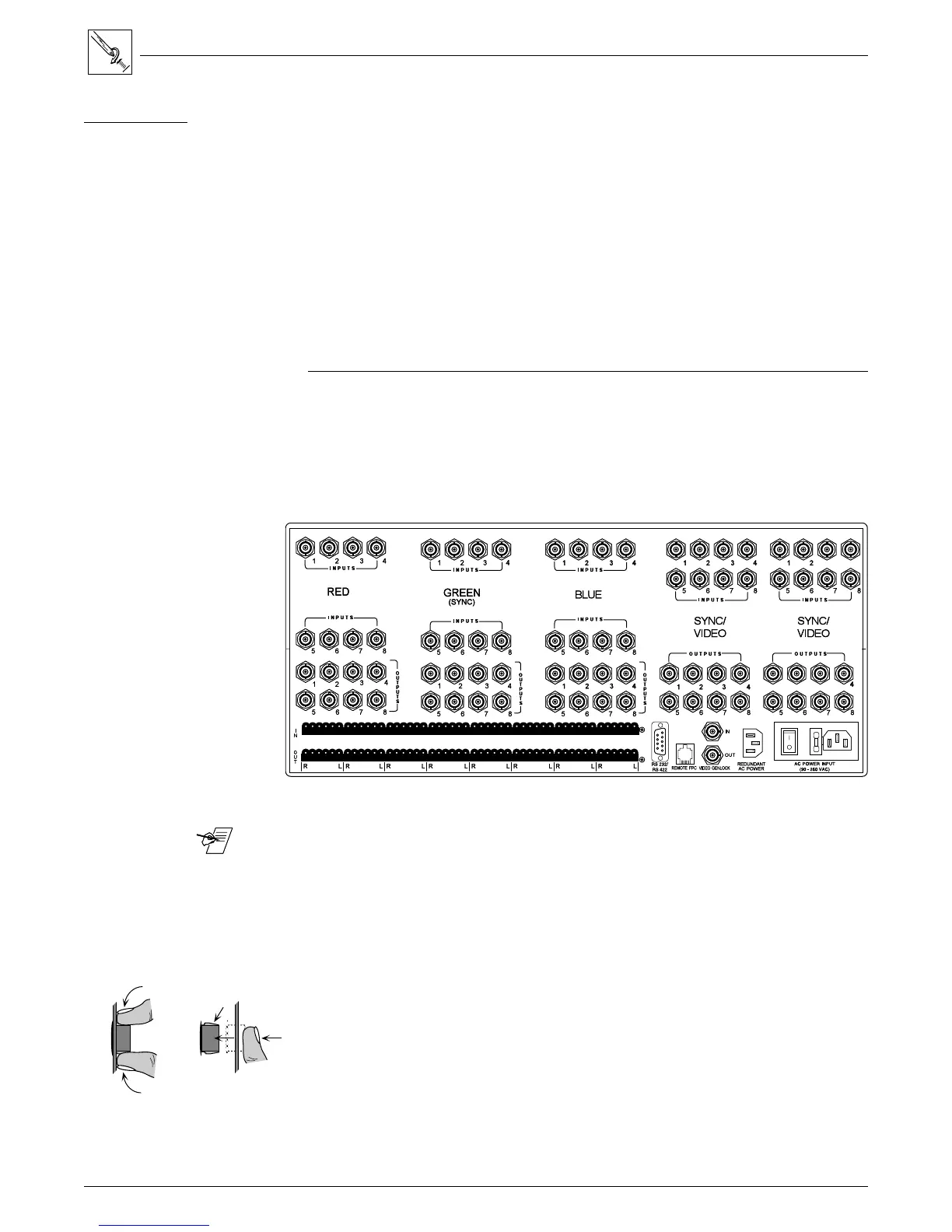
Figure 4-17. This illustration shows the modules already installed.
_______ Address switches are set according to the physical location.
Back panel markings, such as "Sync" or "Video" should show what is installed in
the Matrix 100. If an I/O module was added or changed to another type, peel off
the black covering to show the proper module identification.
1. Remove the Matrix top cover (procedure on page 4-2).
2. Locate the gray ribbon cables that connect the Main Controller board to the
existing I/O modules and determine where the new module will be
connected. If cables from adjacent modules are in the way, they may be
unplugged and reconnected later.
3. On the rear panel, remove the round plastic plugs (as many as required) from
the holes where the new module will be installed. (See Figure 4-20.)
Figure 4-18. Squeeze the tabs to release the plug.
4. On the new module, remove the nuts from the BNC connectors.
Tools for Installation:
3/16" flat screwdriver
#4 Phillips screwdriver
#6 Phillips screwdriver
9/16" Socket/nutdriver
4-9
Squeeze
Locking
Tabs