DTP CrossPoint 4K Series Matrix Switchers • Installation 14
Serial and IR Insertion Connections
RS-232 IR
Tx Rx Tx RxG
78
DTP CROSSPOINT 108 4K
OVER TP
INPUTS
INPUTS
OUTPUTS
RS-232 IR
Tx Rx Tx RxG
RS-232 IR
Tx Rx Tx RxG
0
OVER TP
RS-232 IR
RS-232 IR
Tx Rx Tx RxG
RS-232 IR
Tx Rx Tx RxG
RS-232 IR
Tx Rx Tx RxG
OVER TP
8
RS-232 IR
Tx Rx Tx RxG
RS-232 IR
Tx Rx Tx RxG
OVER TP
Tx Rx
RTSCTS
GTxRxG Tx Rx G
EXP
+48V
MIC/LINE
1
1
3
2
4
2
3
4
LINK
LAN 2
LAN 1
LAN 3
R
AUDIO OUTPUTS
AMP OUTPUT
CONTROL
1234G
DIGITAL I/OCOM 3COM 2
AUDIO INPUTS
COM 1
S
DMP EXPANSION
SGG
1
1
2
2
C34C
-S G+S+V
PWR OUT = 6W
1
LR
1
LR
3
LR
3
LR
5
LR
2
LR
4
LR
2
LR
4
LR
6
LR
IR/SERIAL eBUSRELAYS
1
CLASS 2 WIRING
70V
Tx Rx G
RESET
REMOTE
LAN
123456
1 2 3 4 5A 6A
XTP
DTP
HDBT
SIG LINK
OUT
5B 6B
XTP
DTP
HDBT
SIG LINK
OUT
6
S/PDIF
OUT
XTP
DTP
HDBT
7
SIG LINK
OUT
8
XTP
DTP
HDBT
SIG LINK
OUT
XTP
DTP
SIG LINK
IN
XTP
DTP
XTP
DTP
SIG LINK
IN
SIG LINK
IN
XTP
DTP
SIG LINK
IN
50-60 Hz
100-240V ~
3.0 A MAX
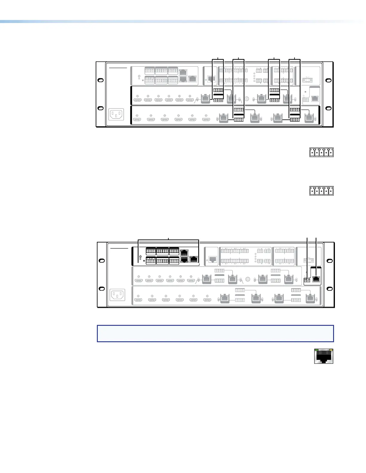
Figure 6. Serial and IR Insertion Connections
O
Over TP (inputs 7 through 10) ports — If desired, connect serial RS-232
signals, modulated IR signals, or both to these 3.5 mm, 5-pole captive screw
connectors to insert bidirectional RS-232 and IR communications onto the
associated inputs (see Serial and IR port connectors on page 20 to wire
the cables).
P
Over TP (outputs 5 through 8) ports — If desired, connect serial RS-232
signals, modulated IR signals, or both to these 3.5 mm, 5-pole captive screw
connectors to insert bidirectional RS-232 and IR communications onto the
associated outputs (see Serial and IR port connectors to wire the cables).
Control Connections
Tx Rx
RTSCTS
GTxRxG Tx Rx G
Tx Rx G
LAN 2
LAN 1
LAN 3
DTP CROSSPOINT 108 4K
R
CONTROL
1234G
DIGITAL I/OCOM 3COM 2COM 1
SSGG
1
1
2
2
C34C
-S G+S+V
PWR OUT = 6W
IR/SERIAL eBUSRELAYS
REMOTE
LAN
EXP
+48V
MIC/LINE
1
1
3
2
4
2
3
4
LINK
AUDIO OUTPUTS
AMP OUTPUT
AUDIO INPUTS
DMP EXPANSION
1
LR
1
LR
3
LR
3
LR
5
LR
2
LR
4
LR
2
LR
4
LR
6
LR
1
CLASS 2 WIRING
70V
RESET
RS-232 IR
Tx Rx Tx RxG
XTP
DTP
XTP
DTP
123457 86
OVER TP
INPUTS
INPUTS
RS-232 IR
Tx Rx Tx RxG
RS-232 IR
Tx Rx Tx RxG
XTP
DTP
XTP
DTP
0
OVER TP
RS-232 IR
Tx Rx Tx RxG
SIG LINK
IN
SIG LINK
IN
SIG LINK
IN
SIG LINK
IN
50-60 Hz
100-240V ~
3.0 A MAX
1 2 3 4 5A 6A
XTP
DTP
HDBT
OUTPUTS
SIG LINK
OUT
5B 6B 6
RS-232 IR
Tx Rx Tx Rx
XTP
S/PDIF
OUT
DTP
HDBT
G
RS-232 IR
Tx Rx Tx RxG
OVER TP
XTP
DTP
HDBT
78
RS-232 IR
Tx Rx Tx Rx
XTP
DTP
HDBT
G
RS-232 IR
Tx Rx Tx RxG
OVER TP
SIG LINK
OUT
SIG LINK
OUT
SIG LINK
OUT
R QS
Figure 7. Control Connections
NOTE: Figure 7 shows features of all models. Actual models have either a LAN port (
Q
)
or a control processor (
R
), but not both.
Q
LAN port (non-IPCP model) — If desired, for IP control of the switcher,
connect the matrix switcher to a PC or to an Ethernet LAN via this RJ-45
connector (see TP connectors on page 17 to wire the connector). You can
use a PC to control the networked switcher from anywhere in the world using
any of the following methods:
• SIS commands (see Using the Command and Response Tables on page 55)
• The Extron Product Configuration Software (see Product Configuration Software
on page 76)
• The DSP Configurator program (see DSP Configurator Program on page 82)
• Built-in HTML pages (see HTML Operation on page 141)


 To Next Page