DD
A
A
WER
.
A MAX
NFI
B EXTENDER PL
D
POWER
12V
1.0A MAX
PAIR
CONFIG
USB EXTENDER PLUS D T
BB
CC
WER
.
NFI
B EXTENDER PL
D
POWER
12V
1.0A MAX
PAIR
CONFIG
USB EXTENDER PLUS D R
A
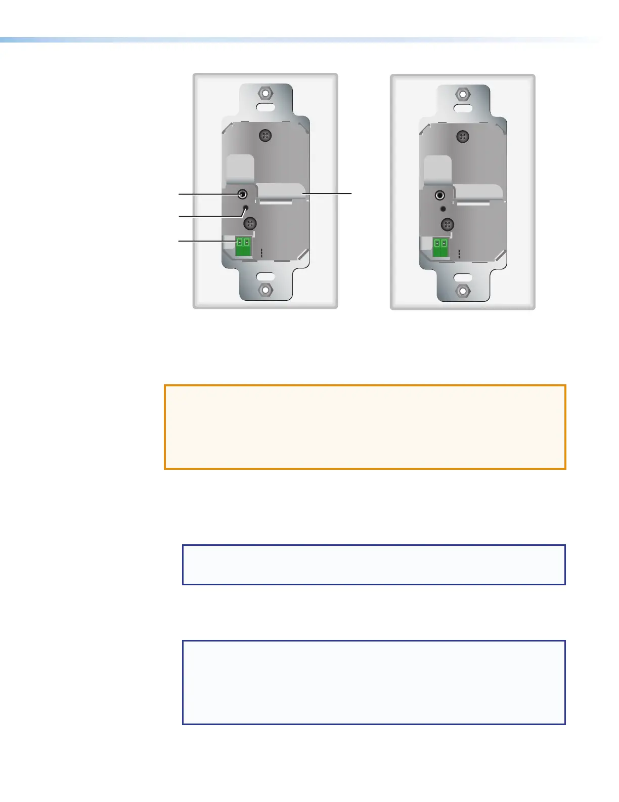
Config port
C
Power connector
B
Pair button
D
Twisted pair output connector
Figure 7. Rear Panel — USB Extender Plus D Transmitter and Receiver
ATTENTION:
• The USB Extender Plus Decorator-Style transmitter and USB Extender Plus TR
Decorator-Style Receiver are to be installed in UL Listed outlets or junction boxes
with the provided faceplate or a UL Listed faceplate.
• Installer dans une prise de courant ou un boîtier de raccordement certifié(e) UL avec
le panneau avant fourni ou un panneau avant certifié UL.
A
Config port — Connect a 9-pin D-to-2.5 mm TRS cable from a computer to
this 2.5 mm TRS jack for RS-232 communication (see Connecting for Serial
Communication on page 13). The Config port enables serial communication with
the computer for configuration and control of the transmitter via SIS commands (see
Remote Configuration and Control, beginning on page 22).
NOTE: Because this connector is on the rear panel, you are not able to access it
after the extender has been mounted. All communication via this port must be
done before mounting.
B
Pair button — This recessed button pairs the transmitter with the receiver. Use a small
screwdriver or stylus to press this button (see Pairing and Unpairing the Transmitter
and Receiver (Point-to-Point Only) on page 12).
NOTES:
• Pairing is required only for point to point non-network applications. For other
types of applications, use PCS to set up the connection (see Using the
Configuration Software, beginning on page 27, for more information).
• For point-to-point non-network applications, pairing must be done before
operation the first time the transmitter and receiver are used together.
USB Extender Plus Series • Installation and Operation 8