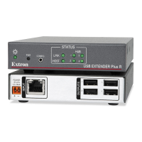
HOST
HOST
Extron
STATUS
LINK
AA
DD
EE
FF
A
Power LED
E
Link LED
D
Host port
F
Host LED
Figure 17. Transmitter Front Panel, D Model
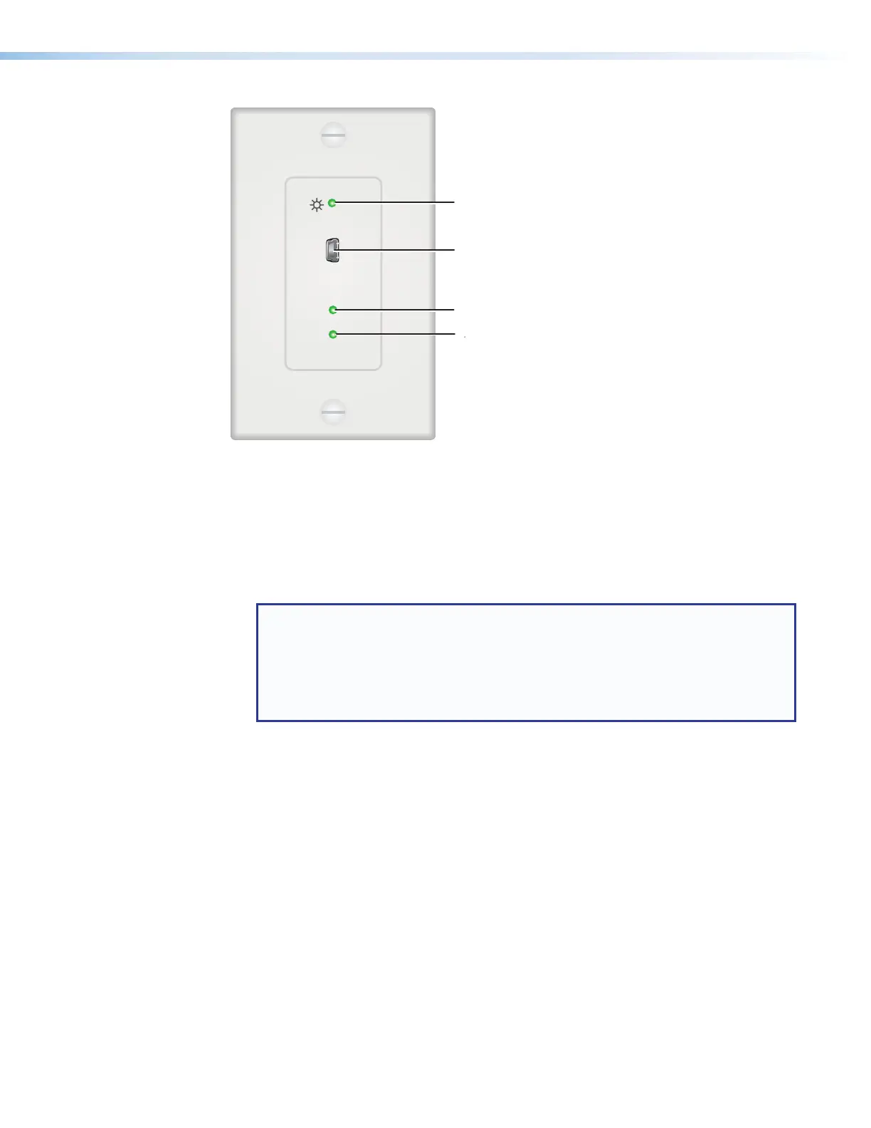
A
Power LED — This green LED lights to indicate that the unit is receiving power.
B
Pair button — This recessed button pairs the transmitter with the receiver. Use a small
screwdriver or stylus to press this button (see Pairing and Unpairing the Transmitter
and Receiver (Point-to-Point Only) on page 12).
NOTES:
• Pairing is required only for point to point non-network applications. For other
types of applications, use PCS to set up the connection (see Using the
Configuration Software, beginning on page 27, for more information).
• For point-to-point non-network applications, pairing must be done before
operation the first time the transmitter and receiver are used together.
C
Config port — (Rack-mountable models only) Connect a 9-pin D-to-2.5 mm TRS
cable from a computer to this 2.5 mm TRS jack for RS-232 communication (see
Connecting for Serial Communication on page 13). The Config port enables serial
communication with the computer for configuration and control of the transmitter via
SIS commands (see Remote Configuration and Control, beginning on page 22).
D
Host (input) port — (AAP and D models only) Connect a USB type A to mini-B cable
from a computer USB port to this USB mini-B connector. The USBExtender Plus is
USB3.0 compliant and supports data transfers of 480 Mbps (high speed), 12Mbps (full
speed), and 1.5Mbps (low speed).
E
Link LED — This green LED lights when the transmitter and receiver are successfully
paired, connected together by the twisted pair cabling, and receiving power.
While the transmitter is being paired with the receiver, this LED blinks. When the pairing
process is completed, the LED lights steadily.
F
Host LED — This green LED lights when the transmitter is powered and is
communicating with the host PC.
USB Extender Plus Series • Installation and Operation 18