PATHWAY
®
Aluminum Wheelchair Ramp Kit Assembly Manual Page 18 of 40
1
4.3.3.
Level the bracket using a bubble level or similar tool, then torque the 5/16”-18 nylon insert
locknuts to 20 ft.-lbs.
4.3.4.
Locate the appropriate PSLxxPR (SUPPORT LEG PAIR where “xx” denotes the leg length)
for the location. Place a foot under the bracket with the foot extending under the ramp,
then insert a 1-1/2” square Support Leg (“leg”) through the bracket into the foot.
Loosen the 3/8”-16 headless socket set screws and the foot thumb screw if needed to
fully engage the leg in the foot (FIG. 4.6).
If installing on soft soil it may be necessary to set the foot on a concrete pad.
4.3.5.
After the leg is fully engaged in the foot, tighten the 3/8”-16 headless socket set screws
to 15 ft.-lbs. (FIG. 4.6).
Do not attempt to walk on the ramps until all leg set screws have been tightened as
specified.
4.3.6.
Tighten the foot thumb screw and insert a 1-1/2” square plug into the top of the leg (FIG. 4.6).
4.3.7.
Repeat the above procedure at all locations where ramps connect.
4.3.8.
Adjust the ramp legs one at a time.
4.3.9.
Raise the ramp sections (at the Center Saddle Bracket) to take any sag out of the ramp
run, then tighten the two locknuts in each leg.
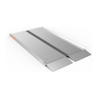
ADA guidelines call for a maximum slope of 1:12 (approximately 5 degrees), and this is
the ideal slope for the system. However, the ramps can be installed from 1:14 to 1:8
(approximately 4 to 7 degrees). Do not attempt to install the ramps outside this range.
Adjusting sections can be accomplished by having someone sight down the ramp
while another person adjusts the ramp height.
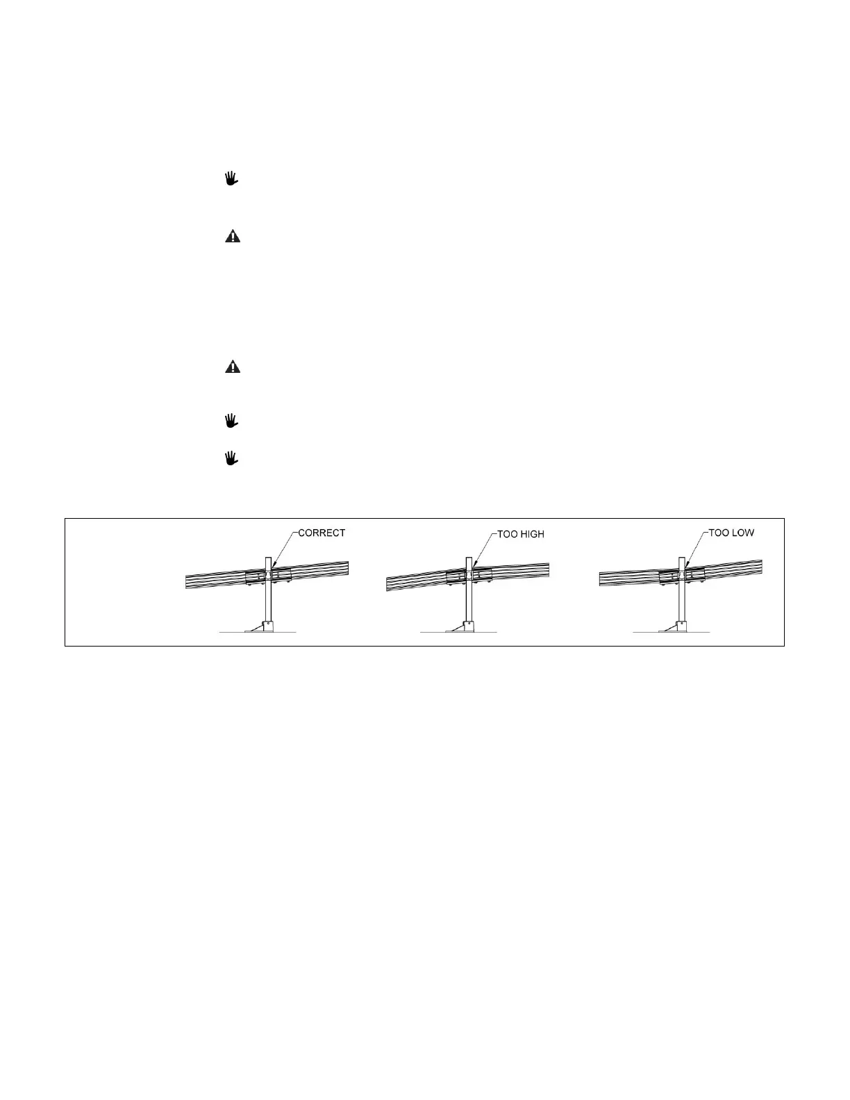
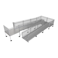
Ensure that the ramp sections are parallel to each other. If they are not, it may be
difficult to install the handrails (FIG. 4.7).
4.3.10.
Ensure that all bolts are tight and that the ramp sections are aligned parallel to one another.