PATHWAY
®
Aluminum Wheelchair Ramp Kit Assembly Manual Page 11 of 40
1
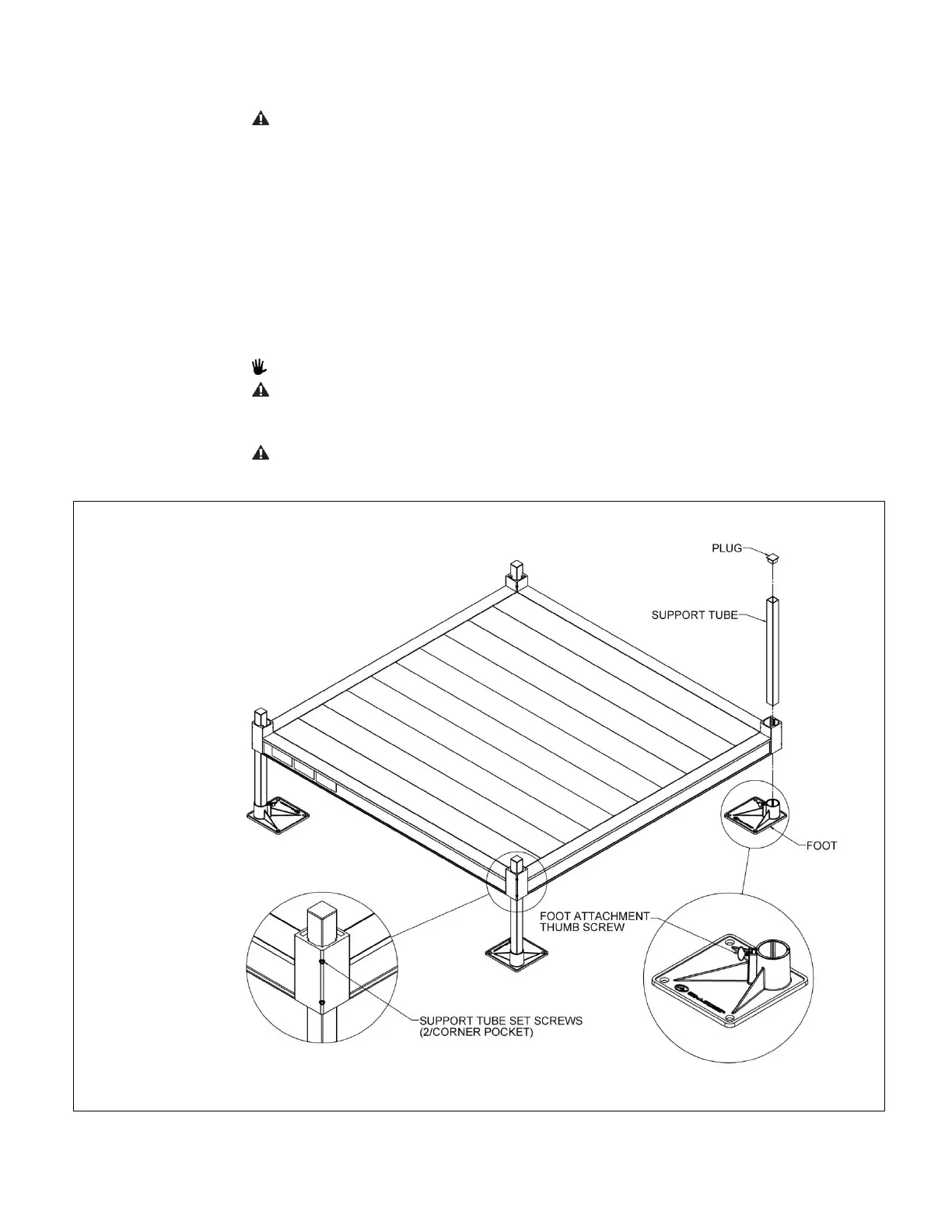
3.2. INSTALL SUPPORT TUBES AND FEET, THEN ADJUST PLATFORM HEIGHT
3.2.1.
Support tubes, plugs, and feet come in pairs. Support tubes will come in lengths
sufficient to accommodate a range of slope options.
ADA guidelines call for a maximum slope of 1:12 (approximately 5 degrees) and this is
the ideal slope for the system. However, the ramps can be installed from 1:14 to 1:8
(approximately 4 to 7 degrees). Do not attempt to install the ramps outside this range.
3.2.2.
Loosen all set screws in the platform corner pockets.
3.2.2.1 The set screws on the outside of the platform are for the platform support tubes.
3.2.2.2 The set screws on the inside of the platform (one above the deck and one below
the deck) are for the handrail posts.
3.2.3.
Tip the platform on its side, then slide the support tubes into the four platform corner
pockets (FIG. 3.4). Adjust the support tubes to the approximate platform height needed.
3.2.4.
Use a 3/16” Allen wrench to tighten the upper of the two set screws in the corner
pocket, just enough to hold the support tube in place but do not overtighten (the
second set screw will be tightened after final height adjustments are complete).
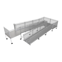
Platforms configured in a U-shape (FIG. 3.3) will have six tubes to adjust.
Do not attempt to walk on the platform until all support tube set screws have been
tightened securely.
3.2.5.
Place the platform (with support tubes attached) into the upright position.
Do not let the weight of the platform bear on the support tubes while tipping the
platform upright.